In order to adapt to the digital isolator propagation delay CAN node bit timing upgrade
The Controller Area Network (CAN) is defined by the ISO 11898 standard and is widely used in industrial and automotive applications. CAN protocols such as DeviceNet or CANOpen rely on built-in error checking and differential signal sampling. Galvanic isolation further enhances robustness against high voltage transients but increases propagation delay. The CAN node is optimally configured to have maximum data rates and transmission distances even when isolated.
Why is propagation delay important?
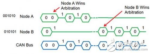
Propagation delays affect concurrent transmissions and arbitration between nodes. Punching relies on CAN signaling; logic 0 means "active" (differential voltage between buses), and logic 1 means "passive" (all outputs are high impedance), meaning that the active bit will override the passive bit. At the time of transmission, all nodes monitor the bus; when the passive bit is transmitted, it stops, allowing another node to win arbitration (node ​​A in Figure 1).

Figure 1. Arbitration between two nodes
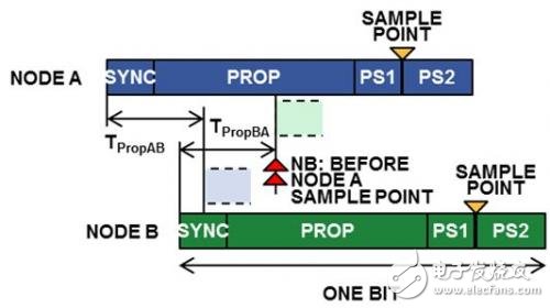
The propagation delay must not be too large, otherwise the bus state may be monitored before other nodes propagate the active state. For Node A and Node B in Figure 2, the round trip time is critical; this time is equal to TPropAB plus TPropBA, or equal to twice the delay time through the cable and transceiver, including isolation (if any). Digital isolators reduce propagation delays compared to optocouplers, but the total propagation delay allowed by the system is fixed, so adding isolation may reduce the maximum cable distance.

Figure 2. Arbitration with propagation delay
Propagation delay compensation
To compensate for the propagation delay caused by the isolation, specific CAN controller parameters can be adjusted. The baud rate prescaler (BRP) value is first set for the CAN controller clock, which defines the "time quantum" (TQ) that divides the bit time. They apply to 3 or 4 segments, as shown in Figure 3; one for synchronization, the other for propagation delay (PROP) and phase segments 1 and 2 (PS1 and PS2). PS2 and total TQ indicate the sampling point position.
Step 1: Match the clock, prescaler, and data rate
For a given data rate, the first step is to check how the clock and BRP are combined to make TQ equal to an integer. The 1 Mbps example is shown in Table 1. This example uses the ADI ADSP-BF548 Blackfin microprocessor with a built-in CAN controller. With a typical system clock (fsclk) value, the TQ integer value is shown in bold (for a valid clock/BRP combination of 1 Mbps).

Table 1. Clock and BRP combinations for 1 Mbps
Step 2: Position configuration
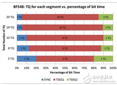
The next step is to define the bit segments and set the sampling points as late as possible. For each valid option in Table 1, the SYNC segment must allow one TQ, and the TSEG2 (PS2) segment must accommodate the CAN controller processing time (as long as the BRP is greater than 4, BF548 is less than 1 TQ). TSEG1 (PROP + PS1) is 16 TQ (maximum).

Figure 3. Possible BF548 bit segment for maximum propagation delay at 1 Mbps
The third step: calculate the bus length
Figure 3 shows the possible configuration of the ADSP-BF548 when the highest possible sampling point is 1 Mbps. All configurations except the 5 TQ sum are at least 85% sampling points, but the best value is achieved at 10 TQ, where fsclk = 50 MHz and BRP = 5.
The final step is to determine the maximum propagation delay in the optimal configuration and determine the possible cable length for the selected CAN transceiver/isolation. For the optimal configuration of the processor in Figure 4, the maximum possible propagation delay is 900 ns.

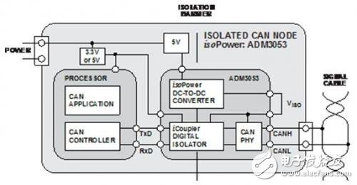
Figure 4. Isolated CAN node with ADM3053, integrated isoPower
The ADI ADM3053 in Figure 1 integrates a CAN transceiver, a digital isolator, and an isolated power supply. The 250 ns loop delay includes the isolator delay (500 ns for two nodes). Assuming a cable propagation delay of 5 ns/m, this means that with BF548, the bus length can be up to 40 m (1 Mbps maximum according to ISO 11898).
in conclusion
Isolation increases robustness, but it also increases the propagation delay in both the transmit and receive directions, and doubles for two nodes during arbitration. To compensate for the delay, the CAN controller can be configured for the maximum possible propagation delay. In this way, it is possible to achieve the required data rate and bus length, even in the case of isolated nodes.
24V Frequency Transformer,110V 60Hz To 220V 50Hz Transformer,Oil-Filled Electric Transformer, electronic oiled transformer
IHUA INDUSTRIES CO.,LTD. , https://www.ihua-inductor.com