Research on Application of Packet Network Circuit Simulation Equipment
1 Introduction
With the rapid development of the Internet, IP networks, with their ubiquitous nature and cost advantages, show great potential advantages in transmitting real-time services such as voice and video.
TDMoP (TDMoverPacketNetwork), also known as packet network circuit emulation device, is a new technology developed based on TMD and IP technology. It can directly adapt all types of services currently running on TDM circuits to IP networks. In the meantime, while taking full advantage of the low cost of the data network, it can achieve a seamless connection with the existing TDM terminal equipment and combine the two organically. TDMoP devices allow operators to maximize their packet-switching infrastructure revenue while selling voice services, and thus have broad application prospects. Based on the introduction of TDMoP principles and technical characteristics, this article focuses on the typical application of packet network circuit simulation equipment in various communication environments.
2. Principles and Technical Features of TDMoP
TDMoP is a technology that enables inexpensive transmission of voice and leased circuit services (such as video, data, etc.) over IP networks. It can also maintain the reliability and quality of service of the public telephone network (PSTN).
TDMoP uses the "tunneling" principle to implement transparent transmission of TDM circuits over IP: E1 synchronization bitstreams are packetized at the source end, followed by IP headers, encapsulated into IP packets, and transmitted over IP networks to destinations. The synchronous clock signal is regenerated at the destination, and then the IP header is removed, and the other data is converted into an E1 synchronization bit stream and transmitted. For transmission of E1 services over packet switched networks, jitter smoothing and clock synchronization are problems that must be addressed.
In the IP network, packets arrive at the destination with a random delay. This delay is called jitter. The jitter of the E1 packet mainly depends on the delay caused by the store and forward in the switch. TDMoP uses a fixed-length package. The length of the E1 data in the Ethernet packet is set to N×32 bytes, which is exactly N E1 frames. The value of N should be properly selected because the delay is too large if the packet is too long, and too heavy if the packet is too short. Dithering can be overcome by using buffers. Since the TDM circuit has a constant bit rate, the faster arriving packets must be buffered before being output, so that the delay difference with other slower packets can be compensated. The cache is set to absorb packet jitter, and the larger the capacity, the larger the jitter. However, increasing the cache linearly increases the voice delay, so you should minimize the buffer while accommodating packet jitter.
In the buffering process, the original clock reference information cannot be extracted. Therefore, the necessary clock synchronization technology is adopted in the TDMoP technology. The clock recovery algorithm is directly related to the stability of the product. The industry generally adopts the packet statistics method to recover the clock. This algorithm generates clock oscillation because of the impact of packet loss. In addition, the statistics require time, so there is a problem of clock convergence. Muqing Technology's TDMoP device adopts a remote measurement algorithm to achieve near-end recovery algorithm to achieve synchronization, the algorithm does not have statistics, the remote sampling of the local clock detection, extraction of accurate TDM signal clock, plus the clock tag and TDM signal package together In the data packet, the receiver can read the clock tag information as soon as it receives the data packet and immediately recover the clock to achieve network synchronization. Remote measurement is implemented using differential clock recovery, which ensures that the TDM circuit stays synchronized at the destination node without any buffer slippage. Practice has proved that this algorithm is superior to similar algorithms in performance. The following discussion focuses on the typical application of TDMoP in various communication environments.
3. Typical Application Research of TDMoP
3.1 Application of TDMoP in Mobile Communication System
In a mobile communication system, a communication connection between a base station (BTS), a base station controller (BSC) and a mobile services switching center (MSC) is called Backhaul. In the planning of future 3G networks, it has been proposed that the design of a cellular backhaul network can effectively reduce the overall cost of building 3G networks.
Backhaul is a major part of the operating costs of mobile networks. The industry generally agrees that 40% to 75% of the total cost of the transmission part may be the return cost. It is particularly important to point out that mobile network operators must balance the cost, availability, and availability of selected access platforms to meet the anticipated increase in bandwidth capacity and reduce the complexity of voice and data convergence networks.
There are generally three ways to communicate between BTS and BSC and between BSC and MSC:
The first is a traditional cable transmission method, that is, renting telecommunication E1 lines or laying themselves;
The second type is optical cable transmission. Special optical cables must be laid to transmit data from BTS to BSC, and an optical transceiver must be configured.
The third type is wireless transmission, using microwave technology or the "TDMoP+ wireless bridge" approach described in this article.
The first two methods all belong to wired transmission. In terms of the first method, leased lines will have higher costs in the long run, and self-laying lines also have the problem of high cost; in terms of the second method, geography The environment has a certain impact on the construction of the network. In particular, in some places with poor conditions, for example, the base station is at the top of the mountain or there is a river barrier, etc. The wired method will have some difficulties or economic waste. As far as wireless transmission methods are concerned, most of them use microwave equipment to transmit in reality, but due to their transmission methods, transmission services, networking modes, and prices, it is difficult to promote them in large areas.
The “TDMoP+ wireless bridge†approach discussed in this paper can effectively control the cost of the wireless mode and make the backhaul design of the cellular network more flexible and efficient. From the transmission point of view, the wireless bridge adopts the IP packet transmission mode, so it can be retransmitted when the wireless interference is lost, and the microwave will generate a bit error. From the perspective of the transmission service, the “TDMoP+ wireless bridge†mode can be transmitted. E1 can also transmit IP services at the same time. At present, most microwave devices can only transmit E1 services. From the perspective of networking mode, the “TDMoP+ wireless bridge†mode can implement point-to-multipoint, convenient networking, and microwaves generally only Peer-to-peer networking; On the cost side, “TDMoP+ Wireless Bridge†has obvious advantages over microwave devices; in addition, this solution also has information security advantages because the clock information is recovered from the network, even if other The device steals the IP data packets that are being transmitted. Because the clock information cannot be obtained, the E1 signal cannot be recovered.
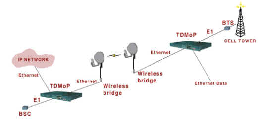
The application of TDMoP equipment and wireless bridge combination in mobile communication system (GSM, CDMA, SCDMA and WCDMA network) is shown in Fig. 1. Muqing Technology's TDMoP equipment has achieved satisfactory results in the current actual test.

Figure 1 Application of TDMoP+ Wireless Bridge in Mobile Communication System
In summary, by adopting the “TDMoP+ wireless bridge†mode, mobile network operators can aggregate traffic from GSM base stations and connect them to BSC through packet-switched networks, operators can transmit Ethernet/IP at low cost, and thus effectively Reduce the return costs of mobile communications networks.
3.2 Application of TDMoP in GEPON
The rise of the Internet and the development of multimedia services have led to an explosion in the demand for network capacity. At present, the construction of the optical fiber has basically been completed in the "core network" part, and it is advancing to the access network. Finally, the entire network of the FTTH will be opticalized. With the decrease of the cost of optical fiber, the "active and passive integration" of optical access networks has become a trend.
Ethernet has been widely used in local area networks, metropolitan area networks and wide area networks due to its advantages of convenient use, low price and high speed. If the access network also adopts Ethernet technology, it will form an all-Ethernet structure, which can achieve seamless connection between the networks, which will greatly improve the network operating efficiency and reduce costs. PON (passive optical network) uses passive optical power splitters/couplers to support point-to-multipoint user network topologies, providing high bandwidth, good reliability, economy, easy expansion, and expansion of new services. The development direction of fiber access technology.
As an important solution for fiber access networks, EPON (Ethernet + Passive Optical Network) is supported and approved by operators and manufacturers at home and abroad, and provides reliable end users with far more bandwidth than existing access technologies. The data, voice and video communications can more completely solve the problem of broadband access. A typical EPON system consists of OLT (Optical Line Terminal), ODN (Optical Distribution Network), ONU/ONT (Optical Network Unit) and EMS (Network Element Management System). EPON adopts the passive optical transmission mode, the up and down speed can reach 1Gbit/s at present, so also call GEPON.
The OLT usually has L2 switching or L3 routing functions. It provides optical interfaces for passive optical networks in the downlink direction, and sends data to ONUs in broadcast mode. GE (Gigabit Ethernet) interfaces, SDH/SONET interfaces, and E1 interfaces are provided in the upstream direction. The OLT is the control center of the EPON system and provides network concentration and access functions. Bandwidth allocation, network security control, and management configuration are performed according to different requirements of the user QoS.
ONU adopts Ethernet protocol to realize the transparent transmission of user data. The ONU supports the traditional TDM protocol and implements access to the traditional voice service by supporting the E1 interface.
ODN is mainly connected to the OLT and ONU by one or more passive optical fiber splitters POS. Its function is to distribute downlink data and centralize uplink data. Because it is a passive operation, the environment has strong adaptability, simple maintenance, and multi-level cascading.
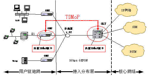
Although bandwidth requirements for data services are growing rapidly, existing circuit services still have a large market and will remain the main source of revenue for business operators in the next few years. In the EPON system, the fixed bit rate real-time service is well supported. Combining the packet switching service with the circuit switching service will facilitate the market application of the EPON and meet the needs of different services. The EPON system initially provides only Ethernet data transmission services and adopts an Ethernet frame structure. To achieve E1 data transmission and guarantee the service quality of real-time services, special processing must be performed. Access network users demand circuit services mainly to provide E1 circuit interfaces. It can be known from the principles of TDMoP that TDMoP cards can be embedded in OLTs and ONUs of GEPON systems to implement E1 access, and they can be integrated with other companies. In the test, the practical application effect of this scheme is also satisfactory. The application of TDMoP in the GEPON system is shown in Figure 2.

Figure 2 E1 circuit simulation in GEPON system
The GEPON access network is a perfect combination of the link layer Ethernet and the physical layer PON technology, and has the unique advantages of a passive optical network structure and the low cost advantages of Ethernet. With the advent of IPTV, network-based interactive services, and the advent of the FTTH era, GEPON technology combined with TDMoP technology will surely usher in a huge market development space.
3.3 Application of TDMoP in WiMAX
The full name of WiMAX is Worldwide Interoperability for Microwave Access, a wireless metropolitan area network technology based on the IEEE 802.16 standard. It is a new air interface standard proposed for microwave and millimeter wave bands. It is used to connect 802.11a wireless access hotspots to the Internet. It can also connect companies and homes to wired backbone lines. It can replace existing wired and DSL connections to provide last-mile wireless broadband access. WiMAX will provide wireless broadband connections in the form of fixed, mobile, and portable forms, and will eventually be able to provide mobile wireless broadband connections without direct line-of-sight base stations. In a typical 3 to 10-mile radius unit deployment, the WiMAX Forum-certified system is expected to provide up to 40 Mbps per channel for both fixed and portable access applications, and can be used by hundreds of business users or thousands of users supporting T1 connection speeds simultaneously. Use DSL connection speed for home users' needs and provide enough bandwidth. Mobile network deployment will be able to provide up to 15Mbps capacity in a typical (highest) 3km radius cell deployment. WiMAX technology is expected to be used in laptops and PDAs in 2006, creating a "MetroZones" between urban areas and cities to provide users with portable outdoor broadband wireless access. According to reports, WiMAX's wireless data transmission speed will reach 70 Mbps, and the transmission distance can reach 50 kilometers. In comparison, the most advanced WLAN can only reach 54 Mbps and several hundred meters, while 3G is still in the hard time. Can reach 2Mbps and dozens of kilometers.
The WiMAX fixed application mode addresses the following users and scenarios: enterprise users, cell E1/IP bearer lines; WLAN public access networks uplink to metropolitan area network lines; and mobile network communication between base stations and base station controllers; There are places where Internet access is required and users are scattered, such as rural areas and remote areas. Wireless broadband access networks are used as an alternative to DSL; places without wired network resources; places where wired networks cannot be accessed, such as restrictions on topography or historical and historical sites Area; link backup; emergency communications.
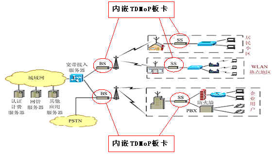
The network topology of WiMAX fixed application mode is shown in Figure 3.

Figure 3 Typical application of wimax with embedded TDMoP board
The wireless part of the network includes a BS and several SSs. The BS is connected to the metropolitan area network and the PSTN. The SS aggregates IP data and voice traffic of multiple users and transmits the traffic to the BS over the air interface. In a typical broadband wireless access network, a WiMAX base station communicates with all subscriber units located at the client through a point-to-multipoint wireless Ethernet connection. The base station can also send the communication back to another WiMAX base station located in the central office. In the central office, TDM communications are brought together in the PSTN (Public Switched Telephone Network). In order to convert circuit-switched services and their associated timing and signaling information into Ethernet packets and seamlessly transmit them over packet networks, we propose to use packet circuit emulation technology and integrate TDMoP cards in base stations and WiMAX terminal equipment. In this way, operators can transmit circuit-switched voice and T1/E1 services over WiMAX IP networks, thereby avoiding expensive traditional service access lines. The TDMoP board supports the requirements of individual households for basic POTS (Plain Old Telephone Service) access, as well as commercial customers' requirements for T1/E1 and non-integral frame T1/E1 services.
3.4 Application of TDMoP in RPR
RPR is a new halo technology for data (especially Ethernet). Unlike SONET/SDH, which is a dual ring configuration, in which one ring is used as a backup ring, RPR is used at the same time at any time and is reversed. To prevent possible congestion, RPR introduces QoS parameters so that the service with the highest priority obtains the bandwidth it needs first and is not affected by the disconnection. Low-priority services may have delays, but since metropolitan area network services are now mainly data rather than voice, the requirement for low network latency is no longer critical. The RPR is eight times faster than SONET/SDH for processing services. First, because time slots can be reused, the same time slot can be used to transmit different data on different network segments; secondly, packets transmitted in any direction are Get to your destination as fast as you can. Since RPR is media-independent and scalable, it uses distributed management, congestion control and protection mechanisms, and has the capability of sub-service level, so it can allocate bandwidth and process data more efficiently than SONET/SDH, and can reduce operators and their enterprises. The cost of the customer, it has become one of the most eye-catching focuses of the new technology.
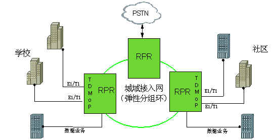
In order to solve the problem of effectively transmitting TDM services on RPR, we propose to encapsulate TDM services with TDM Packet Circuit Emulation (TDMoP) first, and then use RPR to carry encapsulated TDM services. From the point of view of RPR generation, it is to meet the needs of the exponential growth of data services (the metropolitan area network becomes a bottleneck), and the future trend is that data services account for 80% and voice services account for 20%. We are just in order to meet this need. Present this model. This model can not only effectively use the advantages of RPR to efficiently transmit data services, but also can effectively carry TDM services on the RPR. Therefore, it is particularly suitable for occasions where data services are dominant and voice services are supplemented.
The use of packet circuit simulation to achieve TDM service transmission has several advantages. First, it is simple and simple means low cost. Since TDMoP is a tunneling technology, it does not require special instruction functions, but only uses those already existing in the packet network. The function is fine, TDM control signaling and data are transmitted through the tunnel. The second is more coarse-grained. Essentially, TDMoP is not switched at a single channel level, but at the circuit level. These switched circuits can be T1/E1, T3/E3, or even OC3/STM-1 or more. High, this improves the efficiency of network management and control. The third is shorter delay and narrower bandwidth. The delay time of the simulation circuit is usually shorter, because the simulation circuit can form a large grouping in a very short time. For example, a T1 connection includes 24 channels, so constructing a payload containing 192 bytes requires eight frames (1 millisecond). The use of narrower bandwidth means that more bandwidth can be allocated to data services to accommodate future high-speed data service transmission needs.

Figure 4 Typical application of RPR with embedded TDMoP board
4 Conclusion
To sum up, TDMoP realizes the transparent transmission of traditional circuit services on packet networks, giving full play to the advantages of low-cost data networks, thereby effectively reducing costs and improving network utilization. With the wide application of TDMoP in various communication environments, TDMoP will surely usher in a larger market development space.
The products can provide various specifications of rectifier bridge devices according to customer requirements. The electrical properties, appearance, reliability, safety indicators and environmental protection indicators of the products all meet the relevant standards.
Planar Die Construction Sealed Glass Case Ideally Suited for Automated Insertion - 75V Nominal Zener Voltages
Case: MiniMELF, Glass Terminals: Solderable per MIL-STD-202, Method 208 Polarity: Cathode Band Approx. Weight: 0.05 grams= 25°C unless otherwise specified Symbol Pd VF RqJA Tj, TSTG Value to +175 Unit mW V K/W °C
Characteristic Forward Voltage = 200mA Thermal Resistance, Junction to Ambient Air (Note 2) Operating and Storage Temperature Range Notes:
1. Tested with Pulses, 20ms. 2. Valid provided that Electrodes are kept at Ambient Temperature.
1. Tested with pulses = 20 ms. 2. Valid provided that electrodes are kept at ambient temperature.
VZ, ZENER VOLTAGE (V) Fig. 1, Zener Current vs Zener Voltage
25 20 VZ, ZENER VOLTAGE (V) Fig. 8, Zener Current vs Zener Voltage
TA, AMBIENT TEMPERATURE (°C) Fig. 3, Power Dissipation vs Ambient Temperature
15 20 VZ, ZENER VOLTAGE (V) Fig. 4, Differential Zener Impedance
VZ, ZENER VOLTAGE (V) Fig. 5, Junction Capacitance vs Zener Voltage
MINI MELF,Smd mini melf,zener mini melf,mini melf package,mini melf resistor,mini melf diode,mini melf resistor datasheet
Changzhou Changyuan Electronic Co., Ltd. , https://www.changyuanelectronic.com