Use of XILINX FFT IP (continued)
Fourth, Symbol and I / O Description
The input and output signals of the FFI IP are as follows:
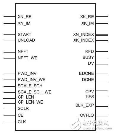
The left side is the input signal of the FFT IP, and the right side is the output signal of the FFT IP.
The specific pin descriptions are as follows:
1. XN_RE: Input signal, the real part of the input data bus, input in 2's complement form, bit width 8~24 bits.
2. XN_IM: Input signal, input imaginary part of the data bus, input in 2's complement form, bit width 8~24 bits.
3. START: Input signal, FFT start signal, active high. After this signal goes high, data loading and calculations begin.
4. UNLOAD: Input signal. For Burst I/O structures, this signal will begin to output the result of the processing. This signal is not necessary for pipeline structures and bit-reverse output.
5. NFFT: Input signal, used to change the transform length (ie, the number of points) when configuring the application in real time.
6. NFFT_WE: Input signal, enable signal of NFFT port, high active.
7. FWD_INV: Input signal to indicate whether to calculate positive or inverse transform, FWD_INV =1 is FFT transform, FWD_INV =0 is IFFT transform.
8. FWD_INV_WE: Input signal, enable signal of FWD_INV port, active high.
9. SCALE_SCH: Input signal. This signal is useful in the IP core design if the intermediate data is reduced during the calculation. The input bit width is 2 x NFFT (base 2 structure and base 2 Lite structure) or 2 x ceil (NFFT/2) (base 4 structure and pipeline structure), where NFFT is the width when the transform length is expressed in binary.
10. SCALE_SCH_WE: Input signal, enable signal of SCALE_SCH port, active high.
11. CP_LEN: Input signal, Cyclic prefix length, size 0~ (transform length -1), useful when cyclic prefix inserTIon is valid.
12. CP_LEN_WE: Input signal, enable signal of CP_LEN port, active high.
13. SCLR: Input signal, optional asynchronous reset signal, active high.
14. CE: Input signal, optional clock enable signal, active high.
15. CLK: Input clock.
16. XK_RE: Output signal, the real part of the output data bus, output in 2's complement form. When SCALE_SCH_WE is valid, the output bit width is equal to the input, otherwise the output bit width is equal to the input bit width + NFFT+1, where NFFT is the conversion length binary Indicates the width of the time.
17. XK_IM: Output signal, the imaginary part of the output data bus is output in 2's complement form. When SCALE_SCH_WE is valid, the output bit width is equal to the input, otherwise the output bit width is equal to the input bit width + NFFT+1, where NFFT is the conversion length binary Indicates the width of the time.
18. XN_INDEX: Output signal, subscript of input signal. The bit width is equal to the width of the transform length expressed in binary.
19. XK_INDEX: Output signal, subscript of output signal. The bit width is equal to the width of the transform length expressed in binary.
20. RFD: Output data valid signal, high effective.
twenty one. BUSY: Status busy indication signal, output high level when conversion is in progress.
twenty two. DV: Data valid indication signal, output high level when there is valid data on the output port.
twenty three. EDONE: The advanced DONE signal, active high, one clock before the DONE signal goes high.
twenty four. DONE: Completion signal, active high, goes high after the FFT is completed,
25: CPV: Cyclic prefix valid signal, high effective. Useful when the cyclic prefix inserTIon is valid.
25: RFS: The signal has been prepared. It is active high. It can start receiving the START signal when the RFS goes high. It is useful in the cyclic prefix inserTIon and pipeline structure.
26. BLK_EXP: Output signal indicating the scaling ratio of each block of data in the block floating-point structure.
27. OVFLO: Output signal, algorithm overflow indication. When the data is output, if the frame has an overflow, the signal goes high.
The above briefly introduces the input and output signals of the FFT IP. You can refer to it when customizing the IP. Detailed instructions can be viewed when the IP is customized.
A metal dome array & sheet (dome array) is a kind of glued PET array & sheet that carries metal dome, which will be peeled easy from the released paper and place sticky on circuit boards, as a switche of electronic device. So it also need "peel & place metal dome", in viewing of metal dome packing. You can put single dome or several metal dome per array, as per designed purposed, mostly the same quantity and location as PAD of circuit board which will be sticked on.
Metal Dome Array,Snap Dome Array,Double Layer Dome Array,El Metal Dome
CIXI MEMBRANE SWITCH FACTORY , https://www.cnjunma.com