Sensorless vector control technology for efficient motor control continues to evolve
Advanced modeling techniques for motor and power stage dynamics can dramatically improve motor control efficiency and ensure precise control based on real-time changes in system behavior. Sensorless vector control technology allows designers to enhance the performance of their motor systems, reduce power consumption, and meet new regulatory requirements designed to increase energy efficiency. A new motor control solution based on a new generation of digital signal processing technology is expected to accelerate the use of advanced control solutions.
In the past decade, with the continuous development of permanent magnet materials and the increasingly easy exploitation of resources, high-performance variable-speed motors have been used in industrial applications using permanent magnet synchronous motors (PMSM). Innate advantages of using PMSM drives include: high torque to weight ratio, high power factor, faster response, rugged construction, ease of maintenance, ease of control, and high efficiency. High performance speed and/or position control requires accurate determination of the shaft position and speed to synchronize the phase excitation pulse with the rotor position. Therefore, speed and position sensors such as absolute encoders and magnetic resolvers are required on the motor shaft. However, in most applications, these sensors can cause a variety of drawbacks, such as: reduced reliability, vulnerability to noise, increased cost and weight, and more complex drive systems. Sensorless vector control eliminates the need for a speed/position sensor, so these problems no longer exist.
In recent years, regarding the sensorless speed and position control methods of PMSM, various solutions have been proposed in the research literature. Three basic techniques have been developed for PMSM-driven sensorless rotor position estimation:
Various techniques based on back electromotive force (BEMF) estimation based on state observer and extended Kalman filter (EKF) technology Other technologies based on real-time motor modeling
Back EMF technologyPosition estimation based on back electromotive force technology estimates magnetic flux and velocity based on voltage and current. This technique is particularly sensitive to stator resistance in the lower speed range. Since the back electromotive force of the machine is small and the nonlinear characteristics of the switching device generate system noise, it is difficult to obtain actual voltage information about the machine terminal. In the mid-high speed range, a better position estimate can be obtained using the back EMF method, but not in the low speed range.
The magnitude of the back EMF voltage is proportional to the rotor speed, so the initial position cannot be estimated at rest. Therefore, starting from an unknown rotor position may be accompanied by a temporary reverse rotation or may cause a startup failure. The EKF is capable of performing state estimation on nonlinear systems in a random noise environment, and thus appears to be a viable and computationally efficient candidate for PMSM speed and rotor position estimation.
The technique based on spatial saliency tracking utilizes magnetic saliency and is suitable for zero speed operation, which can estimate the initial rotor position without being affected by other parameters. There are two basic methods for the initial rotor position, based on pulse signal injection and sinusoidal carrier signal injection, respectively.
Let's look at an example.

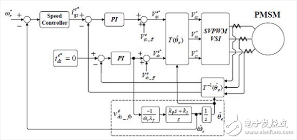
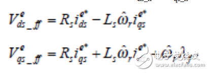
Figure 1 is a block diagram of a sensorless vector control scheme that does not include a position sensor. In the block diagram, the positive feedback terms Vds_ and Vqs_ of the inter-axis control can be expressed as:

Where ωr
For the speed of the rotor.
Looking at the standard voltage formula of the built-in PMSM (IPMSM), the coordinate system can be expressed as:

Where θerr is the difference between the actual angle and the estimated angle.
Now reposition the d axis, you can get:
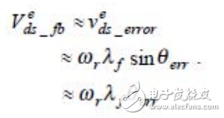
Assuming that the current PI regulator will produce small errors, θerr is small and the d-axis can be expressed as:

In the proposed estimator of Figure 1 and the derived formula, the error signal Vds_error is processed by the PI compensator to derive the rotational speed of the rotor, and the angle of the rotor is calculated by integrating the estimated velocity. Other common methods use the differential method to calculate speed, but this makes the system susceptible to noise. Experimental studies by Bon-Ho Bae have shown that the estimator is recommended to provide very accurate and reliable speed information for the application. However, at zero speed and low speed, the back EMF voltage is not high enough to be used for the proposed vector control. Thus, for seamless operation from zero speed, the estimator utilizes a constant amplitude and a predetermined mode frequency to control the current. Here, the angle of the synchronous coordinate system is derived by integrating the frequency (initial starting method).
19V AC DC Switching Power Adapter
19V Plug in AC/DC switching power supply were widely used for any small power device, such as CCTV Cameras, wireless routers, LED strip, ADSL cats, HUB, switches, security cameras, audio/video power supply. For 19V wall mount power supply, the maximum output current is 1.89A,total 36W output. Our power adaptor meets different certificates for different countries` request – like UL list/CCC-CQC/ PES/SAA/C-TICK/CB/GB certificate. All our switching power supplies were getting 2-hours burn-in test & 3KV high voltage test during production.

19V AC DC Switching Power Adapter,19V AC DC 90W Switching Power Adapter
Shenzhen Juyuanhai Electronic Co., Ltd. , https://www.powersupplycn.com