555 police car audio circuit original schematic
The sound circuit diagram of the 555 police car is as follows. A1 generates low frequency oscillation, and its frequency f1=0.7~14.4Hz. The specific value is adjusted by the potentiometer RP. Capacitor C1 (capacitor is usually referred to as a capacitor, denoted by the letter C. Capacitor is a 'charged container', is a device that holds a charge. Capacitance is one of the most widely used electronic components in electronic devices, widely used for blocking The charging circuit of the coupling, bypass, filtering, tuning loop, energy conversion, control circuit, etc.) is supplied by Ra, RP, and a diode VD is connected in series in the discharge loop, so it is generated on C1. A series of sawtooth waves with a range of high to low. The oscillation frequency of A2 is about 870Hz, and the duty ratio is 47%. This circuit is buffered by the VT of the A1 pin 2 and pin 6 of the A1, and the sawtooth wave of C1 is added to the control end of the A2 (5 pin). The wave modulates the high-frequency square wave so that A2 produces a high-to-low oscillating frequency, and the speaker emits a continuous "correction-correction-" sound.
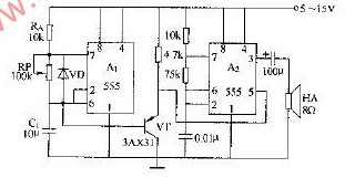
555 police car audio circuit diagram
An electronic clock device with a wireless network monitoring camera is characterized in that it comprises an electronic clock device body with a wireless network monitoring camera; the electronic clock device body with a wireless network monitoring camera is composed of a foot, a wireless transmission module, a It consists of a rechargeable battery, a speaker, a touch display screen, a camera, a casing, an infrared device, and a microprocessor; the feet are fixedly installed at the bottom of the rechargeable battery; a casing is fixedly installed on the top of the rechargeable battery, and the The interior is provided with a touch screen, a camera, an infrared device and a microprocessor; the microprocessor is electrically connected to the rechargeable battery through wires; the wireless transmission module, speaker, display, camera and infrared device are connected to the micro processor through wires The display screen is arranged at the bottom of the camera, and the camera is surrounded by an infrared device; the wireless transmission module is fixedly installed on both sides of the rechargeable battery, and the speakers are opened on both sides of the casing
Wifi Electronic Clock hidden camera,hidden camera wifi,hidden camera wireless,spy camera wifi
Jingjiang Gisen Technology Co.,Ltd , https://www.gisengroup.com