Application of lFS200 Electrical Fire Monitoring System in Power Distribution Lines of Coal Mines
Application of lFS200 Electrical Fire Monitoring System in Power Distribution Lines of Coal Mines
Abstract : According to the characteristics of coal fires in coal mines, Henan Lean monitoring and control technology has proposed a distributed master-slave electrical fire monitoring system using computer networks and intelligent control technology to provide temperature, current, voltage and leakage currents for distribution lines. The signal is automatically detected. A kind of electrical fire monitoring system based on rs485 bus and sTM32 single-chip microcomputer is designed. The composition and hardware and software design of the system are described.
Keywords: electrical fire monitoring system; leakage current
0 Overview
In recent years, many coal mine fire accidents have caused major losses to coal mining companies. In order to avoid casualties and economic losses caused by electrical fires, electrical fire monitoring systems must be installed on the power distribution lines of coal mining enterprises. Force Security Technology developed the LFS200 electrical fire monitoring system and the GDS3000 mine safety monitoring and management system for this problem. The electrical fire monitoring system uses micro-processing and bus technology, effectively improving the system's security and reliability.
1 The overall structure of the electrical fire monitoring system
The electrical fire monitoring system consists of multiple electrical fire monitors and electrical fire centralized monitors. The Rs485 bus is used as a communications network to connect multiple electrical fire monitors and electrical fire centralized monitors into a host and slave distributed monitoring system.
2 Electrical fire monitoring system functions
2.1 The electrical fire monitoring system can monitor the temperature, three-phase current, residual current and three-phase voltage signals on the power distribution line in real time.
2.2 The electrical fire monitoring system can display the temperature, three-phase current, residual current and three-phase voltage values ​​on the power distribution line and the address of the electrical fire monitor on the bus.
2.3 The parameters of the electrical fire monitoring system function settings include the address of the electrical fire monitor, the alarm value of the leakage current, the temperature alarm value, the overcurrent alarm value, the overvoltage and undervoltage alarm values, and the phase loss alarm.
2.4 Electrical fire centralized monitor obtains slave information by polling the electrical fire monitor. When the measured value in the protected power supply line reaches or exceeds the set value, it can send an alarm signal and pass the trip. The coil cuts off the circuit.
3 Electrical Fire Monitoring System Hardware Design
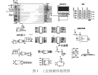
3.1 The centralized monitor of electrical fire has microprocessor module, LED display module, keyboard input module, trip coil control module, sound and light alarm module, information storage module and RS485 communication module.
The schematic diagram of the electrical fire centralized monitor hardware is shown in Figure 1. The system uses STM32F103RBT6 microcontroller. The character-type liquid crystal display module 12864 connects the LCD controller, the RAM, the ROM, and the LCD display with the pCB. The required prompts can be realized by simply sending the corresponding commands and data to the lCM. All kinds of parameter setting information and fire alarm information of the electric fire centralized monitor need to be stored for reference. Therefore, the upper computer of the electrical fire monitoring system uses the E2prom chip 24c02 to realize the performance of various information power-off preservation and no loss.

3.2 Electrical Fire Monitor
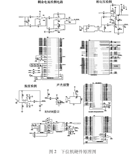
The electrical fire monitor has a temperature monitoring module, a leakage current monitoring module, a phase current monitoring module, a phase voltage monitoring module, an audible and visual alarm module, and an Rs485 communication module.
Electrical fire monitor hardware schematic shown in Figure 2. The lower position machine takes SMT32F2812PCFA as the controller, expands the peripheral circuit, realizes the real-time data acquisition, calculation, signal processing.

3.2.1 Leakage current acquisition and conditioning circuit
Residual current acquisition using residual current transformer. The three-phase line and neutral line of the power distribution line pass through the toroidal core to form the primary coil of the transformer. The winding on the toroidal core constitutes the secondary side of the transformer. If leakage occurs, the three-phase phase line and the neutral If the current vector of the line does not equal zero, an induced electromotive force is generated on the secondary side of the transformer. This signal is sent to the intermediate link for further signal amplification.
3.2.2 Voltage Acquisition and Conditioning Circuits
The voltage u of each phase of the power supply line is converted into a current I1 of 0 to 1 mA through R1. I1 flows through the primary winding of the voltage transformer, generates a current I2 at the secondary side of the voltage transformer, and generates a voltage signal F through the parallel resistance R2.
This voltage signal is filtered and clipped to the A/D conversion channel of the microcontroller.
3.2.3 Temperature Acquisition and Conditioning Circuits
Temperature sensor uses pt100 resistance temperature monitor. The principle of using the constant current source temperature measurement circuit in this system is as follows: The op amp is pulling the R2 resistor up to the 1.65V reference source Uref. The op amp inverting input voltage Utemp is equal to the reference source Uref and forms a constant current source through the ground resistance R1. The A/D of the microcontroller samples the Utemp voltage and determines the resistance of the pT100. ZDI is a Zener diode. Its role is to prevent the high voltage from directly connecting to the A/d pin of the microcontroller and damage the SCM chip.
4 Electrical fire monitoring system software design
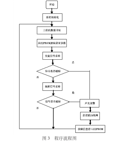
The software program of the electrical fire monitoring system includes a main program, a key interruption subroutine, each AC signal sampling subroutine, a display subroutine, an alarm subroutine, a trip coil control subroutine, and a communication subroutine. After the electrical fire monitoring system is powered on, it first initializes the internal resources of the system, and then reads the preset leakage current, phase current, electrical fire monitor address, phase voltage, and temperature parameters from the E2PROM chip outside the single-chip microcomputer. These preset parameters can be configured via RS485 bus communication. Subsequently, the electrical fire monitoring system samples the leakage current, three-phase current, three-phase voltage signals, and temperature signals on the power supply and distribution lines respectively. If the acquired real-time signal exceeds the preset alarm value, the fault processing subroutine is entered. Including sound and light alarm, and cut off the circuit through the trip coil. Finally, all the information at the time of the failure is saved to the external E2PROM chip for later inquiry. The main program flow chart shown in Figure 3.

5 RS485 bus
In this system, the electrical fire monitoring centralized controller (host) electrical fire monitor is a slave and constitutes a master-slave configuration. Through the software protocol, the host and the monitor implement a responsive communication method. Commands or data transmissions can only be controlled by the host. At any one time, the host only transmits information with one monitor, and the monitor cannot directly communicate with each other. Communication between monitors can only be forwarded by the host. Each monitor has a unique eight-digit address number to distinguish each monitor. The host communicates with the monitor through a point name to implement master control over the communication system. The host continuously polls the monitor to monitor the status of the monitor, introduce the monitor request or send various commands to the monitor.
6 Conclusion
The main function of the electrical fire monitoring system mentioned in the article is to monitor the current, voltage, leakage current and temperature signals of the coal mine power supply and distribution lines, substation equipment and important electrical equipment before the fire occurs. Based on the alarms of the addresses of hidden dangers and faults, and timely recording and saving of relevant information. The promotion and popularization of this electrical fire monitoring system in coal mine enterprises is of great significance to the reduction of electrical fires and the promotion of safe production for coal mining enterprises.
Laptops,windows Laptops,win11 Laptops,win10 Laptops
Jingjiang Gisen Technology Co.,Ltd , https://www.gisengroup.com