AT89C2051 control voice chip recording and playback system circuit diagram
Voice chip application circuit
The ISD2560 is a type of ISD series single-chip voice recording and playback integrated circuit. It is a permanent memory type recording and playback voice circuit with a recording time of 60 seconds and repeatable recording of 100,000 times. It uses direct level storage technology, eliminating the need for A/D, D/A converters. The ISD2560 is highly integrated and includes internal preamplifiers, internal clocks, timers, sample clocks, filters, automatic gain control, logic control, analog transceivers, decoders, and 480KB of EERPOM. The internal EERPOM storage unit is evenly divided into 600 rows with 600 address units, each of which points to one of the rows, each with an address resolution of 100 MS. The ISD2560 control level is compatible with TTL levels, and the interface is simple and easy to use.
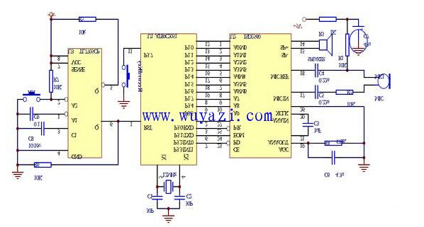
AT89C2051 control voice chip recording and playback system circuit diagram
The ISD2560 has several built-in modes of operation that allow for the most functionality with minimal peripherals. The operation mode also has address control; when the highest bit is 1, the other address selects a mode. Therefore, the operating mode and direct addressing are mutually exclusive. The mode of operation can be implemented by either a microcontroller or hardware. The basic circuit schematic is as follows: Recording Press the recording button to ground, the PD terminal and the P/R terminal are low level, and the recording is started at this time; when the button is released at the end, the MCU has the P/R terminal returned to the high level. Complete a recording of a voice. The same method can take the second paragraph, the third paragraph, and so on. It is worth noting that the recording time cannot exceed the preset time of each speech. The operation of playing the sound is simpler. Press the recording button to connect to the high level, so that the P/R terminal is low to start the square sound function; at the end, release the button to complete a voice playback.
When the sampling MCU controls the voice chip recording, press the record button, the MCU sets the start address of the voice segment through the D port line, and then makes the PD terminal and the P/R terminal low to start recording; at the end, release the button, the MCU Have the P/R end return to the high level, that is, complete a voice recording. The same method can take the second paragraph, the third paragraph, and so on. It is worth noting that the recording time cannot exceed the preset time of each speech.
During playback, according to the voice content to be played, find the corresponding voice segment start address and send it through the line. The P/R terminal is set to low level, and the /CE terminal generates a negative pulse to start the playback. At this time, the MCU only needs to wait for the ISD2560 information end signal. The signal is a negative pulse. At the rising edge of the negative pulse, the speech is played, so the MCU must detect the rising edge to play the second segment, otherwise the played speech will not be continuous. The interface circuit and peripheral circuits of the ISD2560 and the single-chip AT89C2051 ($0.5999) are shown in the figure. The P1 port, P3.4 and P3.5 of the MCU are connected to the address line of the ISD2560 respectively to set the start address of the speech segment. P3.0~P3.3 are used to control the recording and playback status. P3.7 Connect a button for recording. The TL7705 ($0.1875) constitutes a reliable reset and power monitoring circuit.
Although the ISD2560 provides an address input line, the address of its internal information segment cannot be read. The system is controlled by a single-chip microcomputer, and the information address start address is directly set without reading the information address. There are two ways to achieve this: First, because the address resolution of the ISD2560 is 100 ms, the internal timer of the MCU can be used to time 100 ms, and then the counter is counted by a counter. The count value of the counter is the voice segment. The occupied address unit. This method can make full use of the E2PROM inside the ISD2560, and can use this method when there are many fields. Second, if the voice field is small, the address unit can be directly allocated according to the content of each field. Generally, it is calculated by 3 words per 1 s, 180 words can be said for 60 s, and the address unit required for the speech segment can be calculated according to the address resolution of the ISD2560 of 100 ms. This circuit uses the second method.
Commercial Electric Fan,Small Electric Fan,Standard Electric Fan,Electrical Fan
Foshan Shunde Josintech Electrical Appliance Technology Co.,Ltd , https://www.josintech.com