Design scheme of RFID-based anti-theft system based on ARM
This paper introduces the structure of a new generation of automobile anti-theft system based on radio frequency technology, and proposes a design scheme of RFID anti-theft system with ARM microprocessor as the core. The hardware and local part of the radio frequency identification anti-theft system of the car are given in the scheme. The circuit diagram of the component is transplanted with the embedded real-time operating system on the hardware platform, and the driver and application software of the system are written. The laboratory simulation platform is built. The test results on this platform show that the system has good anti-theft function, thus confirming The practical value of this program.
1 Introduction
With the development of RFID technology, car anti-theft devices are becoming more and more rigorous, perfect and easy to use. The development direction of car anti-theft is developing towards a more intelligent chip and network. The anti-theft system based on radio frequency identification technology belongs to the chip anti-theft system, which is a new application of radio frequency technology. The anti-theft system based on radio frequency identification technology has the characteristics of no contact, large working distance, high progress, quick information collection and processing, and good environmental adaptability. This paper focuses on a hardware design based on ARM radio frequency identification anti-theft system. On the basis of hardware system, the embedded real-time operating system is transplanted, which makes the software design of the system more flexible. This system can well overcome the weakness of the battery remote control device used in the market, and effectively achieve the purpose of automobile anti-theft.
2. Anti-theft system principle
In the case that the carrying system has authorized the "key", when the owner tries to enter the car, the door handle is simply pulled, and the system is actively unlocked for the user to enter, and the door will automatically open. This is because when the user opens the door handle or the trunk switch, the sensor device in the car door is triggered to send a low frequency signal containing the password information to detect whether there is an authorized key in a certain range of the car periphery. This test is usually There is a key 1.5~2.0m in the range of the periphery of the car. When the “key†receives the detection signal, it will send the high-frequency encryption signal related to the key correspondingly. After receiving the password signal, the car will check it. If the password is valid, The door lock of the door or the trunk lid will automatically open, the whole process lasts for a short time, and the owner has no feeling. When the owner enters the car, press the engine start button. At this time, the system starts to detect whether there is an authorized key in the driver's driving position. If the password and storage stored in the system are the same as the password in the system, the car engine is started. If it is forced to enter, because the system does not detect the authorized "key", even if the start button is pressed, the car engine will not start, and the car is in a protective state, thus playing the purpose of car anti-theft.
3. Anti-theft system hardware design
3.1 Automotive RF anti-theft system
In this system, the microprocessor is the core component of the system and controls the operation of other components. The radio frequency identification part is an important part of this system and it is responsible for reading the user's legal information.
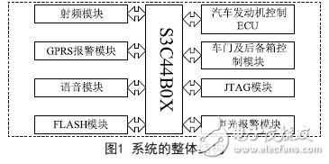
The overall structure of the system is shown in Figure 1. S3C44B0X is the control center of the system, which controls the work of other modules, the radio frequency identification module, and completes the information reading of the authorization key. The GPRS module sends information to the owner through the module when the car is stolen. The voice module realizes the voice prompt to the owner. The automobile engine control ECU mainly controls the start and stop of the engine, and the door and trunk control module is mainly responsible for closing and opening the door and the trunk. The function of the JTAG module is to implement system debugging. The main function of the sound and light alarm module is to realize the system alarm when the car is stolen.

3.2 Design of radio frequency identification system
The RFID system is an important component of the car anti-theft system. The anti-theft part of the car is composed of a radio frequency card, a reader and an RF antenna. The tag consists of a coupling element and a chip, and has a built-in antenna for communication with the RF antenna; the reader can also write tag information in the card, and the RF antenna is used to transmit RF signals between the tag and the reader.
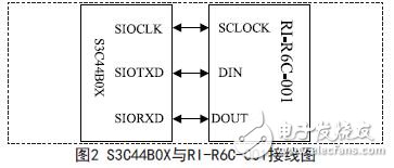
The basic workflow of the system is that the reader transmits a certain frequency of the radio frequency signal through the radio frequency antenna; when the radio frequency card enters the working area of ​​the radio frequency antenna, an induced current is generated, the energy obtained by the radio frequency card is activated, and then the radio frequency card passes the information such as its own code into the card. The antenna is sent out; the RF antenna receives the carrier signal sent from the RF card, and after being transmitted to the reader through the regulator, the reader demodulates and decodes the received signal, and then sends it to the background main system for related processing; The system judges the legality of the card according to the logic operation, and at the same time makes corresponding processing and control for different settings, and issues a command signal to control the action of the actuator. In this system, the RI-R6C-001 radio frequency read/write chip is selected. The transceiver (RI-R6C-001A) combined with the MCU completely implements the upper layer protocol for VICC operation specified by ISO/IEC15693-3. The physical layer protocol of VCD and VICC communication specified by ISO/IEC15693-2 is implemented by the internal ASIC of the transceiver. The communication interface between the MCU and the transceiver has three lines: SCLOCK, DIN, DOUT, which represent the clock line, data input line, and data output respectively. line. The hardware structure of the system is shown in Figure 2.

power connector is used in power module system. It can select the matching power + signal connector according to the need. The feature is that the number of power and signal contacts and the matching sequence can be selected arbitrarily while keeping the connector size and contact core number unchanged.
Plug (male) / socket (female) can be installed at 90 or 180 degrees. It supports mixed or independent combination of signal and power. The quantity range of power and signal is (2-16) pin and (12-128) pin respectively
Product features
High temperature resistant, glass fiber reinforced and flame retardant polyester is used as insulation material
Copper gold composite conductor with high conductivity is used, and the contact area of the conductor is plated with gold
It adopts shrapnel contact, which has the characteristics of integration, small volume, large current carrying capacity, soft plug-in, blind plug-in, self guidance and high dynamic contact reliability. This series of products can be interchanged with FCI's powerblade series and Tyco's multi-beam series
There are three sizes of center distance of power contact: 5.08mm, 6.35mm and 7.62mm
The length of power hole / signal pin can be selected in two sizes. The power rated current is 45A and the signal rated current is 2.5A
Power+ Signal Power Connector
ShenZhen Antenk Electronics Co,Ltd , https://www.antenkwire.com