How should a high-power broadband amplifier be designed? How to choose a suitable broadband amplifier?
The design of high-power broadband amplifiers is a very challenging task. Engineers need to compromise between multiple opposing design parameters. For an amplifier user, both the initial investment and future operating costs are very important considerations. This article will delve into these requirements and what options are available to achieve these conflicting design goals. For specific applications, suggestions are also given to select the appropriate amplifier and the key design parameters that need to be considered the most.
1 Introduction
Designers of broadband amplifiers need to meet a variety of design requirements. For example, for many applications, broadband amplifiers need to be sufficiently linear and fully reflective at harmonic frequencies. In addition, for non-broadcast TV applications such as radars and military transmitters, the amplifier must also be able to withstand huge mismatches at the output. These are usually caused by the characteristics of the connected antenna, the terminal load, and the reflection of the device under test. . For these applications, the robustness of the amplifier, which means that it is not easily damaged, becomes extremely important. Unmeasurable due to damage to the amplifier means that the project will face serious and expensive delays, and even the laboratory's revenue will be lost.
From a business perspective, both the initial investment and future operating costs are very important. Therefore, high reliability and easy maintenance are the key factors to achieve these goals. In addition, for ultra-high-power broadband amplifiers, in order to reduce operating costs, it is also necessary to improve power efficiency as much as possible. The second part of this article will discuss this in detail.
When looking for an amplifier for a specific application, the most important thing is to be able to explain clearly the various parameters in the data sheet. Different power amplifier manufacturers define power amplifier parameters in different ways. The third part will suggest how to read this parameter and how to compare.
2. Challenges of high-power broadband amplifier design
When designing a high-power broadband amplifier, engineers need to comprehensively consider the bandwidth, gain, output power, and mismatch behavior characteristics under various amplitude and phase conditions, linearity, harmonic characteristics, power efficiency, etc., and find the best Important priority indicators.
Most of these indicators affect each other. For a given transistor type, as the bandwidth of the design increases, the output power that can be obtained decreases. More challenging is that in order to achieve greater output power, matching networks and corresponding power division circuits, power combining circuits will become more difficult. At the same time, the service life of the power amplifier tube is very dependent on the heat dissipation design of the amplifier and the protection circuit surrounding the power amplifier tube.
For class A amplifiers, the transistors are usually biased on a relatively large quiescent current, so that a very linear amplification characteristic can be obtained, but they have to withstand poor power efficiency and put a lot of heat on the transistors. Class AB amplifiers have lower static bias currents than Class A amplifiers, and can also get very good linear characteristics, and much better power efficiency, and the heat dissipation pressure of the transistor is reduced. The push-pull structure is usually used for circuit design.
In order to better understand the impact of thermal stress on the service life of a transistor, we can use the junction temperature behavior characteristics of a typical LDMOS transistor to illustrate, as shown in Figure 1. According to experience, if the junction temperature is reduced by 10 degrees, the life of the transistor can be doubled. If GaN transistors are used, the lowering of the junction temperature has a greater benefit to life. The current power amplifier tube can provide greater RF power density and can achieve a more compact and smaller amplifier. The key to the design is how to design a more efficient heat sink to handle the large amount of heat dissipated by the power amplifier tube. For Class A amplifiers, this is usually difficult to achieve, requiring more transistors and reducing the maximum power output of each transistor to deal with the heat dissipation problem. Even so, Class A amplifiers still have a high junction temperature when there is no RF input. The reason is that they have a large static bias current. When the heat dissipation design is not handled well, the service life will be greatly reduced.
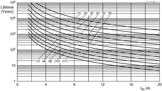
Figure 1. The relationship curve of LDMOS transistor life with drain current at different junction temperatures. Curves 1 to 11 represent the junction temperature from 100 °C to 200 °C, in steps of 10 °C
For some applications, wideband amplifiers are not always required to provide maximum power output, such as EMS testing. Figure 2 shows the calibration curve of the power applied by the amplifier to the EMS antenna versus frequency in a 200V/m EMS system. It can be seen that different power outputs are needed to achieve the corresponding field strength. As described in Figure 2, at 100MHz, the required maximum forward power is about 1050 watts, and at 200MHz and above, the required maximum forward power drops to about 600 watts, and it can even be used for some frequencies. Reduce to about 400 watts. Therefore, in these EMS applications, Class AB amplifiers have better efficiency than Class A amplifiers, and the lower junction temperature of the transistors can bring longer service life.
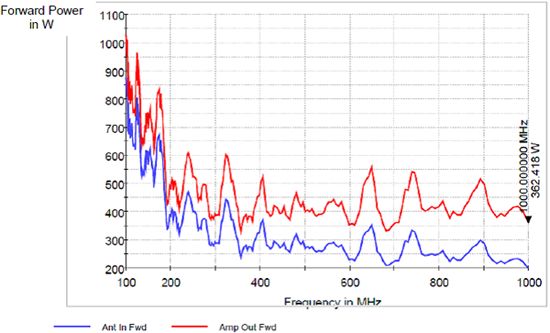
Figure 2. In the EMS test, in order to achieve a field strength of 200 V/m, the forward power that the amplifier output and the antenna input need to achieve at different frequencies
Regardless of the type of high-power broadband amplifier, a high standing wave ratio will also put additional pressure on the transistor. Because the reflected radio frequency power is also dissipated in the amplifier circuit, this further increases the junction temperature of the transistor. In order to avoid the high standing wave ratio from damaging the amplifier, it is necessary to design an efficient power dissipation circuit. This can be achieved through a reasonable layout of the heat dissipation system, including the placement of thermal sensors at the relevant hot spots, or by monitoring the relevant voltage and current of the transistor achieve. In addition, power amplifier designers and product designers have to decide whether to add enough semiconductor power units to ensure that the amplifier can still provide sufficient forward power under a poor standing wave ratio, or allow the amplifier to operate at a certain standing wave Start to fall back than the next. More semiconductor power units mean higher cost amplifiers, and a higher price is needed in the market.
3. Choose the right broadband amplifier
As a user, they don't care about the design challenges that designers have to face, just make sure to choose a suitable amplifier to meet their application. When choosing an amplifier, you will find that there are many indicators that describe the performance of the amplifier. Users not only need to consider technical indicators such as output power and harmonic characteristics, but also need to consider multiple important factors for building and maintaining the entire high-power amplifier system. This will be discussed in detail below.
3.1 Amplifier output power
In order to compare the power amplifier output power indicators of different power amplifier manufacturers, the 1dB compressed output power is usually used as a reference value. This index defines the corresponding output power when the amplifier gain is 1dB lower than the small signal gain. Most manufacturers use the output power within a certain frequency range to nominal the output power of the entire amplifier. In fact, it is not possible to achieve the nominal 1dB compressed output power in all operating frequency bands. Some manufacturers' data sheets The 1dB compressed output power provided is low. Therefore, we must carefully compare the data in the data sheet and figure out the entire output power curve.
For some high-power transmitter applications, the budget of the entire system needs to be considered. Under normal circumstances, the antenna can provide greater gain in the high frequency band, so the amplifier can provide a smaller output power to achieve the required field strength. In this way, purchase and use a smaller amplifier for the upper part of the system frequency band.
3.2 Harmonic characteristics
The harmonic suppression of an amplifier is usually described in dBc. It is very important to confirm at what output power the manufacturer evaluates the harmonic suppression data. Under normal circumstances, it is at 1dB compression power, but some manufacturers evaluate it at low output power, because lower output power can get better harmonic characteristics. In this case, it is difficult to know the harmonic characteristics of the amplifier at the 1dB compression point. Regardless of whether it is a Class A or Class AB amplifier, once it is driven above the 1dB compression point, the harmonic characteristics will deteriorate in a non-linear manner.
Another thing to consider is that you must know whether your application has requirements for harmonic characteristics. For example, the nominal value of harmonic suppression of general amplifiers is around -20dBc, but in fact -15dBc is enough, so that the amplifier can be driven to higher power. Also, if better harmonic characteristics are required, It is necessary to appropriately reduce the output power, or choose a more powerful amplifier.
3.3 System design
When looking for a suitable amplifier, it is very important to decide which amplifier to integrate according to the system environment. For those who need to integrate multiple frequency bands, the RF switch should also be selected, which can be at the input or output of the power amplifier, or even at the power sampling port. Some manufacturers can provide built-in switches, which can avoid external switches and reduce the difficulty of system design. At the same time, remote control can become simpler.
For some receiving or transmitting system applications, such as radars and jammers, it is very useful for the amplifier to be able to silence quickly. Usually it is required to switch between silence and output in a few microseconds, and the output power during silence should be low enough, the closer to the thermal noise floor of -174dBm/Hz, the better, which requires very high design skills, and Not all manufacturers can achieve this, so a more stringent selection of amplifier manufacturers is required.
When designing a system, it is also very important to find the optimal combination of amplifiers in different frequency bands. It is often not the best way to implement it in accordance with the long-standing practice. The best thing is to deeply understand the requirements of the system and know the exact power level required by each frequency band, especially according to the application requirements of the system, to know which frequency band or sub-band must be covered by an amplifier module. Only in this way can we get a plan that is both economical and has excellent technical indicators
3.4 System operating expenses
The operating cost of the amplifier system is mainly determined by the system uptime, the cost of use and maintenance. This cost is the most important item of the cost of ownership in the life cycle of an amplifier, so it must be considered when choosing an amplifier.
The uptime of the system depends on the robustness of the amplifier, for example, it can work normally without failure under severe conditions, and the repair time after a failure occurs. If the amplifier cannot be used normally, critical tasks may be dangerous. The progress of the project will be delayed, and even directly affect revenue.
The use cost of the amplifier mainly depends on the power efficiency. High power efficiency means low power consumption, less heat dissipation, and less processing and heat dissipation costs. In short, it is less use cost. Therefore, for most applications including military EMC, it is recommended to purchase a high-efficiency amplifier, especially when ultra-high output power is required.
In order to maintain a long running time and low maintenance costs, it is best to choose an amplifier manufacturer with good local support and maintenance services. Current amplifiers have a remote control function, which can be accessed through the LAN port for initial fault location and error analysis. This function can make maintenance easier.
Moreover, the amplifier itself is designed to be easier to maintain. For example, the BBA150 modular amplifier of Rohde & Schwarz allows users to replace the amplifier module in a short time. The final suggestion is to choose an amplifier manufacturer with industrial production capacity and providing service support documentation. Only in this way can it be guaranteed that the amplifier can still get good service after several years of use.
4. Summary
This paper describes the challenges faced by designers of broadband power amplifiers during R&D. It is necessary to repeatedly compromise between multiple design indicators that affect each other to get the best results. The difference between Class A and Class AB amplifiers and the influence of thermal stress on the service life of the amplifier are discussed, and suggestions to make the amplifier's standing wave capability stronger are put forward.
The factors to be considered when choosing a suitable amplifier for a specific application are discussed. The data manuals of different manufacturers’ products must be carefully read for performance comparison. The system requirements must be considered when integrating amplifiers. A more economical solution can often be obtained by optimizing the system design. .
When considering the total cost of ownership of the amplifier system, not only the initial purchase cost must be considered, but also the robustness and easy maintenance of the amplifier, which can maximize the total operating time and life and reduce the total cost.
ZGAR Vape Pods 1.0
ZGAR electronic cigarette uses high-tech R&D, food grade disposable pods and high-quality raw material. A new design of gradient our disposable vape is impressive.We equip with breathing lights in the vape pen and pods.
Our team has very high requirements for product quality, taste allocation and packaging design. Designers only use Hong Kong designers, e-cigarette liquid only imports from the United States, materials are food grade, and assembly factory wants medical grade without ground workshop.
We offer best price, high quality Pod System Vape,Pods Systems Touch Screen,Empty Pod System, Pod Vape System,Disposable Pod device,Vape Pods to all over the world.


Pods,Vape Pods,Pod Systems,Atomizer, E-cigarette, Empty Pod Vape Manufacturer and Supplier in China
ZGAR INTERNATIONAL(HK)CO., LIMITED , https://www.zgarpods.com