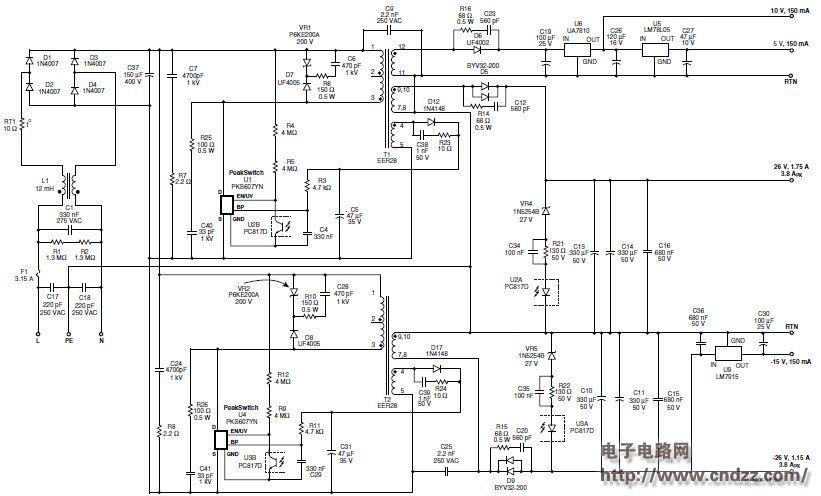
Circuit design of 60W audio amplifier multi-output power supply
Summary:
The universal input power supply has two main output power supplies (+26VDC and –26 VDC) and consists of two parallel converters, each with 30 W of continuous output power and 100 W of peak output power. Both converters use the PeakSwitch device (PKS607YN) and share an input stage. The ±26 V output provides 3.8 A of output current and 1.15 A of continuous output current. Therefore, the two converters add up to 60 W of continuous output power and 200 W of peak output power. Product applications include audio amplifiers that require peak power in a short period of time. The magnitude and duration of the peak current is determined by the duty cycle, ambient temperature, and thermal conditions.
design feature
- Can effectively replace the linear transformer power supply used in home audio systems
- Small number of components, small and light
- High energy efficiency
- More than 75% efficiency at full load (60 W)
- No-load power consumption less than 300 mW at 265 V AC input
- Reduces the use of heat sinks and eliminates the need for a separate standby power supply
- Excellent transient response improves audio quality
- Dual converter for excellent cross regulation between outputs
- The integrated frequency modulation feature combined with a low cost EMI filter enables the design to meet CISPR-22/EN55022B conducted EMI requirements (see Figure 2).
- Integrated safety and reliability:
- Accurate, self-recovering thermal shutdown function keeps PCB temperature within safe conditions under all conditions
- Entering the latched shutdown state when the output short circuit and the feedback loop are open loop
60W continuous output, 200W peak audio amplifier power supply circuit diagram

See the uploading documentation for details (click to download)
Ethernet Slip Ring is a device that allows Ethernet signals to be transmitted through a rotating assembly. This device is typically used in applications where it is not possible or practical to run Ethernet cables, such as in an application where the cables would have to travel through a hazardous area. It converts the regular Ethernet signals into rotary signals, which are then transmitted through the rotating assembly.
There is a growing trend in the industry for Ethernet slip rings. Ethernet slip rings are currently being used to interconnect computer networks. A slip ring is a transmission device that uses a counter-rotating encircling belt to transfer power and data between two or more devices.
Senripgrid Conductive Slip Ring has the following characteristics Direct unplugging of the RJ45 connector Upon reaching eight simultaneous ports, follow the standard cable connection method Work with either copper or gas-liquor joints Transmission to the external network (10M, 100M, 1Km Base T).
Ethernet Slip Ring,Generator Collector Rings,Through Bore Rotary Union,Rotary Pressure Joint
Dongguan Oubaibo Technology Co., Ltd. , https://www.sliproubos.com