Resistance detection circuit analysis
SMD aluminum electrolytic capacitor
Kaixin micro test
AVX tantalum capacitor low resistance TPSD107K016R0100 original 2011+
Test probe P100-M3
Shunuo varistor / ESD varistor / product complete / Sunlord first-class agent
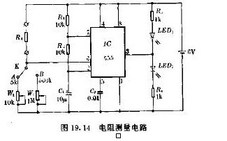
| Figure 19.14 is the circuit for measuring the resistance RX. When W1 or W2 is changed, the voltage of pin 6 of 555 is equal to or higher than two-thirds of the power supply voltage of 6V, C1 is continuously charged and discharged, and the voltage on C1 fluctuates up and down in the third of the power supply voltage of 6V. Shock, LED1 and LED2 will flash alternately. When the voltage of pin 6 of 555 is lower than two-thirds of 6V, C1 will not discharge. Only charging, the voltage on C1 will be charged to 6V, and the output of 555 is always high. Therefore, LED1 is off and LED2 is always on. . According to the above working principle, it can be used to measure RX. The switch K selects the range, the range is 5kΩ when K is turned on A, and the range is 500kΩ when K is turned on. The measured resistance is actually half the value of W1 or W2. According to this range, W1 and W2 are scaled, and the indicated value of W1 and W2 (that is, one-half of the actual resistance) is the RX value. The measurement method is as follows: connect the measured resistor, select the range, adjust W1 or W2, observe the LED1 and LED2 illumination status, and make the two LEDs change from alternating flash (higher flicker frequency, it is difficult to detect flashing) LED1 is extinguished and LED2 is illuminated. At this time, the indicated value of W1 or W2 is the resistance of the resistor RX under test. |
Car Flasher Relay,Led Car Flasher Relay,Pc Car Flasher Relay,Car Electronic Flasher Relay
Ningbo Xingchuangzhi Electric Appliance Co.,Ltd. , https://www.xingchuangzhi.com