Circuit Module Design of Threading Robot Car System
First, the traversing robot car can guide the car to advance along the line on the ground by capturing the signal obtained by the infrared sensor. The information obtained from the infrared sensor is amplified by the signal and sent to the 51 single-chip microcomputer, and the single-chip microcomputer determines the rotational speed of the motor on the left and right sides of the trolley according to the logic judgment. The single-chip microcomputer regulates the rotational speed of the left and right DC geared motors through PWM technology. When the left and right speeds are the same, the trolley runs straight; when the left motor speed is greater than the right motor speed, the car makes a right turn, otherwise the car makes a left turn. . The car is powered by dual power supplies, that is, the control part is powered by 5V DC, while the motor part is powered by 12V DC. Since the motor power is not very large, no photoelectric isolation treatment is used.
The schematic diagram of the circuit design of the 5V power supply of the car is as follows:
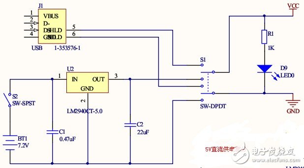
In the design, I originally planned to make the car powered by USB, and can also be powered by the rechargeable battery pack. The specific power supply mode is switched by the S1 switch. Since the USB power supply is a standard 5V DC power supply, the voltage regulator circuit is eliminated. In the circuit powered by the battery pack, when the S2 switch is closed, the voltage provided by the battery pack is regulated by U2 and then intervened in the system. What I have in U2 is the LM2940CT-5.0, which stabilizes the output voltage at 5V output and outputs up to 1.25A. A light-emitting diode of D9 is added to the circuit to indicate whether the power is turned on. A resistor of 1K ohm is connected in series before D9 for current limiting.
Schematic diagram of the circuit design of the 12V DC power supply for the car:
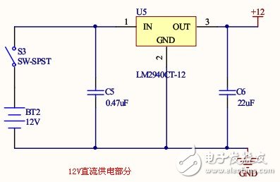
This part of the circuit design is the same as the 5V power supply part, except that the U5 part is replaced by the LM2940CT-12 chip, and the output voltage of this chip is 12V.
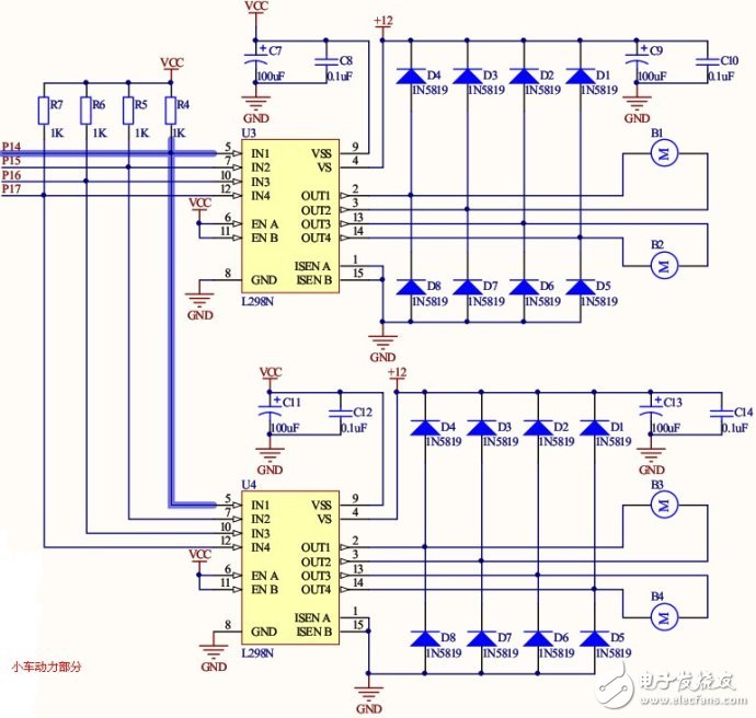
The following is a schematic diagram of the circuit design of the power part of the car:
Electronic Zinc Alloy Die Casting
Electronic Zinc Alloy Die Casting,Custom Die Cast Aluminum,Zinc Alloy Die Casting Stainless,Precision Aluminum Alloy Water Pump
Dongguan Metalwork Technology Co., LTD. , https://www.diecast-pro.com