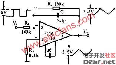
Square wave converted into triangular wave circuit diagram
The figure shows the conversion of a square wave into a triangular wave line using a general-purpose I-type F006 op amp. The illustrated line is as indecent as to put the operation into the form of the integrator, input a square wave flag, and the output can obtain a The triangular wave has a square wave amplitude of 5V, a period of 1MS (that is, a frequency of 1KHZ), a flag with a pulse duty of 50%, and a triangular wave with a peak of 2.5V. The R2 is used to calculate the release night. The low-frequency sinusoidal effect of the device, which is affected by the æº drift, is no longer working as an integrator at low frequencies.
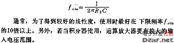
The lower limit frequency F can be obtained by the following formula:
Guangzhou Bolei Electronic Technology Co., Ltd. , https://www.nzpal.com