Conversion error rate decryption of high speed analog to digital converter
Like many other semiconductor devices, high-speed analog-to-digital converters (ADCs) don't always perform as well as we expect. They have some inherent limitations that cause occasional rare conversion errors that go beyond normal functionality. However, many actual sampling systems, such as test and measurement equipment, do not tolerate high ADC conversion error rates. Therefore, it is important to quantify the frequency and amplitude of the high-speed analog-to-digital conversion error rate (CER) so that engineers can design systems with the right expected performance.
The relatively sparse switching errors of high-speed or GSPS ADCs (gigasample ADCs per second) not only make them difficult to detect, but also make the measurement process time consuming. This duration typically exceeds the millisecond range, reaching hours, days, weeks, or even months. To help alleviate this time-consuming test burden, we can estimate the bit error rate with certain "confidence" certainty, while still maintaining the quality of the results.
Bit error rate (BER) and conversion error rate (CER)
Similar to the digital equivalent of the bit error rate in serial or parallel digital data transmission, the conversion error rate is the ratio of the number of conversion errors to the total number of samples. However, there are some differences between BER and CER. The BER test in the digital data stream uses a long pseudo-random sequence that can be initiated in the transmitter using common seed values ​​at both ends of the transmission. The receiver is expected to receive the ideal transmission. By observing the difference between the received data and the ideal data, the BER can be accurately calculated. A mismatch in the pseudo-random sequence data between the two ends (based on the seed value) is considered a bit error.
Unlike CERs, error determination is not as simple as a purely digital comparison. Due to the small nonlinearity of the ADC conversion process and the presence of system noise and jitter, it is not always possible to determine the exact difference between the expected data and the actual data. Instead, an error threshold needs to be established to determine the boundary between the conversion error and the sample with the expected noise. This is different from the digital BER and does not make an exact comparison of the expected data sent and received. Instead, the magnitude of the error in the sample must first be quantified and then determined to be a conversion error or within the expected nonlinear range of the converter and system.
The bit error rate of the ADC's back-end digital interface must be lower than the converter's core CER, so it cannot be ignored. If this is not the case, the data output transmission error will cover the CER and become the main source of error. The system designer does not really care which part of the ADC the error comes from, but for discussion purposes, we will only focus on the ADC conversion error rate.
Metastable
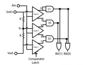
A common cause of conversion errors in high speed ADCs is a phenomenon known as metastable state. High-speed ADCs often use many ladder comparators in different conversion stages that convert analog signals to digital values. If the comparator cannot determine if the analog input is above or below its reference point, a metastable result can result in an error code. This can happen when the difference between the inputs of the two comparators is very small or zero, and a correct comparison cannot be made at this time. Because this error value propagates along the pipeline, the ADC can cause significant conversion errors.
When the differential analog input is a relatively large positive or negative value, the comparator can quickly calculate the difference and give a definitive decision. When the difference value is small or zero, the duration required for the comparator to make a decision can be much longer. If the comparator output latches before this decision point, a metastable result will result.

Figure 1. This basic trapezoidal comparator design gives the probabilistic point (meta-stable) of the transition fault at the comparator decision point. Assuming AIN = VA, the intermediate comparator may not be able to resolve the stable output within the finite conversion time, resulting in multiple possible combinations of errors for bit [1] and bit [0].
Fortunately, some designs can alleviate this problem. First, the most obvious way is to design the comparator's uncertainty range to be very small, forcing the comparator to make an accurate decision within the range of possible maximum analog input conditions. However, this may result in increased circuit power and design size.
The second method is to delay the comparator sampling time as much as possible, and establish the maximum time for the analog input to the known comparator output value. However, there are several limitations to this approach because the longest delay can only last until the end of the current sampling time, and the comparator must continue processing the next sample.
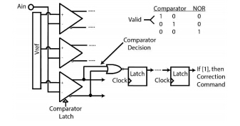
The third method uses an intelligent error detection and correction algorithm that digitally compensates for the uncertainty introduced by the comparator during the subsequent stages of the high speed ADC conversion process. The logic can detect this miss when the comparator fails to make a decision within the maximum allowed time. This information can then be attached to the relevant sample for future internal adjustments. When this alert is recognized, a post-processing step can be used to correct the error before the sample is output from the converter. This can be seen in the AD9625 in Figure 2, which is a 12-bit, 2.5 GSPS ADC from Analog Devices.

Figure 2. Uncertainty of the comparator can be identified during the analog-to-digital conversion process of the AD9625. A correction command can be executed in a subsequent step to correct the sample and then output from the converter.
Ei 76 Transformer,76V Transformer,Ei-76 Transformer,Audio Output Transformer
Guang Er Zhong(Zhaoqing)Electronics Co., Ltd , https://www.cnadaptor.com