Implementation of Modbus protocol based on PLC
With the rapid development of 3C technology, network integrated information automation is being rapidly applied to field devices and controls. Fieldbus control systems are gradually replacing traditional distributed control systems. Modbus fieldbus protocol has been increasingly adopted in PLC-based control systems. The wider the application. In this system, PLC is used as the host, and the temperature acquisition module is the slave, which completes the automatic control of the production process, the display and modification of industrial processes and process parameters. According to the PLC's non-protocol communication function, Modbus The fieldbus protocol realizes the communication between the master and slave.
Based on the design of a monitoring system, this article realizes that the Mitsubishi FX2N series PLC communicates with the acquisition module of the DS18b20 digital temperature sensor in the non-protocol communication mode using the Modbus protocol. During the melting process of the electric furnace, the electric furnace, capacitor, cooling water, etc. More than 100 points of temperature to achieve inspection.
1 System hardware composition
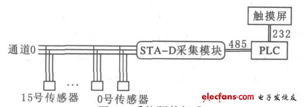
The hardware of the temperature monitoring part system is composed of DS18b20 digital temperature sensor, acquisition module, FX2N series PLC, FX2N-485-BD, and HITECH touch screen. Its structure is shown in Figure 1.

Figure 1 System hardware composition
DS18b20 is the world's first digital temperature sensor that supports a single-wire bus interface (1w ire bus inter face). The single-bus interface facilitates the construction of a distributed temperature measurement and control network. The digital output improves the reliability of signal transmission and makes the peripheral circuit large. For simplicity. DS18b20 has high adaptability and cost performance, its temperature measurement range is -55 ~ 125 ℃, temperature measurement accuracy is ± 0.5 ℃, temperature measurement distance is up to 200 m, temperature measurement method uses 3-wire system, this system uses The sensor sorting method is specified sorting.
DS18b20 mainly has three digital components: a temperature sensor, a 64-bit laser etching ROM, 9 bytes of scratchpad RAM and 3 bytes of EERAM. The 64-bit data on the ROM is the serial number of the sensor. The scratchpad ensures the integrity of the data. The data is first written to the scratchpad and can be read back. After the data is verified, it can be transferred to the EERAM by the copy scratchpad command to ensure the integrity of the data when the memory is changed . The scratchpad is 9 bytes, and the 0th and 1st bytes are temperature-coded low and high bytes.
The second and third bytes are the copy of the low and high bytes of the temperature encoding, and the fourth byte is the configuration register, whose value determines the resolution of the temperature conversion.
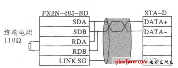
The STA-D temperature acquisition module used in this system is a remote digital temperature acquisition system with 10 channels, and each channel can be connected with up to 16 DS18b20 digital temperature sensors, which can monitor the temperature of 160 points in total. The RS485 mode communicates with the host computer, the communication protocol is the standard Modbus protocol, the baud rate is 9 600 bps, the maximum communication distance with the host computer is 1 200 m, the working power supply is 12 ~ 24 V, and the working temperature is-20 ~ 75 ℃. FX2N ?? 485 ?? BD adopts two-wire 485 connection (Figure 2), and the wiring should use standard shielded wire.

Figure 2 485 connection diagram
Taiwan HITECH company touch screen PWS series is an interactive workstation specially designed for PLC. It is directly connected to PLC with 232, which can directly read the data register of PLC. It has a good man-machine interface, through which the operator can set all parameters and control the system. automatic running. Moreover, the programming is simple, the operation is stable, and different management rights can be set, which is suitable for the use of this system.
2 Modbus protocol
The standard Modbus port uses RS 232C compatible serial interface, which defines the pins, cables, signal bits, transmission baud rate, and parity of the connection port. The controller can be directly or via Mo dem networking. Controller Communication uses master! Slave technology, that is, only one device (master device) can initiate transmission (query), and other devices (slave devices) respond accordingly according to the data provided by the master device query.
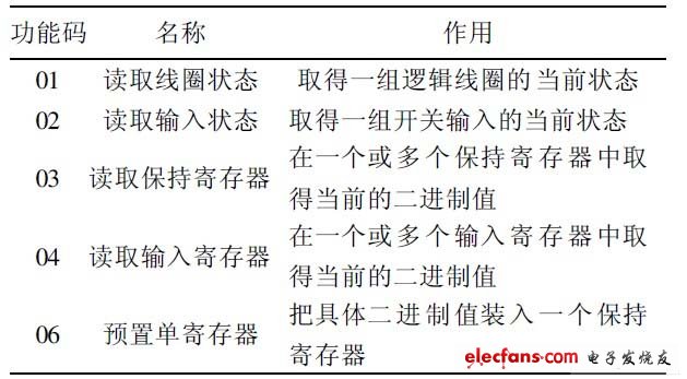
Table 1 Modbus part function code definition

Modbus communication protocol has two transmission methods? RT U mode and ASCII mode. This system uses RTU mode. The main advantage of this method is: Under the same baud rate, more data can be transmitted than ASCII mode.
When using the RTU mode, the message transmission should start at a pause interval of at least 3.5 character times, as shown in T1- T 2- T 3- T 4 of Figure 3. The first field of transmission is the device address, and the transmission characters that can be used are hexadecimal values. During communication, the network device continuously detects the network bus, including the pause interval. When the first field (address field) is received, each device decodes it to determine whether it is destined for itself. After the last transmitted character, there must be a pause of at least 3.5 character times to calibrate the end of the message, after which a new message transmission can be started. A typical message frame is shown in Figure 3. Using RT U mode, the message includes an error detection field based on the CRC method. The CRC field detects the content of the entire message.

Figure 3 M odbus message frame structure
The CRC field is two bytes and contains a 16-bit binary value. It is added to the message after calculation by the transmission device. The receiving device recalculates the CRC of the received message and compares it with the value in the received CRC field. If the two values ​​are different, there is an error. The implementation of the CRC algorithm will be described in detail later.
3 System software composition
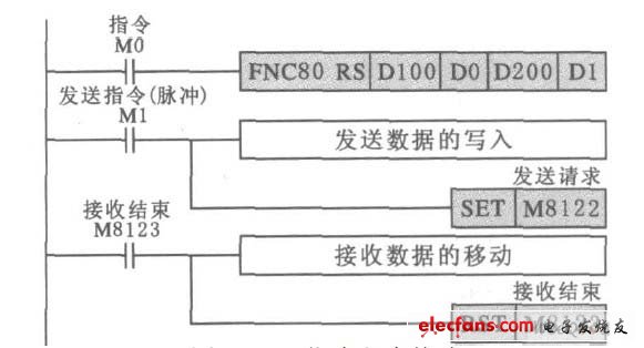
Considering the convenience of operation, when the system is first installed, first search the ID of all sensors on the PC with the host computer software, and then give each sensor number according to the actual installation position, and read whether the temperature test sensor is working properly. When using Modbus protocol communication on the PLC, the communication format must be set first, that is, the write operation of the D8120 register is set to 0C87 under this system condition, that is, the data length is 8 bits, no check, no start bit With stop bits, the baud rate is 9 600 bps. After modifying the D8120 settings, make sure that the PLC power is turned on and off once. Then use RS instruction to transmit data, the relevant program format is shown in Figure 4.

Figure 4 RS instruction program format
Yuchai 0-20KW Diesel Generator
Yuchai 0-20Kw Diesel Generator,Yuchai Soundproof Power Generator,Yuchai Canopy Power Generator,Yuchai Mobile Power Generator
Shanghai Kosta Electric Co., Ltd. , https://www.kostagenerators.com