Virtual reality positioning system based on FPGA
Virtual reality technology is the frontier subject in computer information science. In this paper, a data acquisition and processing system based on FPGA is designed. HMC5883L and ADXL345 are used to determine the orientation and orientation of objects in the virtual scene and give virtual scenes through Ethernet. The host sends data. The whole system uses FPGA as the main controller, with sensor data acquisition, internal FIFO storage, and high-speed Ethernet transmission, so that the positioning system parameters can be transmitted to the host computer in real time, which has the advantages of fast transmission speed and real-time performance. Realized the high-precision positioning of virtual reality.
1 Introduction
Virtual Reality (VR) is an active technology research field in computer applications. It is an emerging technology in the entire information science field. It is based on computer video technology, computer image processing. Computer psychology. Artificial intelligence. Human-computer interaction technology. Sensor technology. Network and display processing A series of information technology branches of the latest results are concentrated. In the virtual reality environment, people can interact with scenes and things in the virtual world, it has penetrated into aerospace. Civil military. Entertainment games. Medical medical and education industries. It is now one of the important technologies affecting human life in the development of the 21st century.
In the whole virtual reality, the positioning of the object in the scene is the key core part. In the positioning, it is mainly to obtain the orientation and position in the rectangular coordinate system where the object is located and the inclination angle of the object and the horizontal plane. For this we use three-dimensional Magnetoresistive sensor and three-axis gravity acceleration to obtain the necessary data.
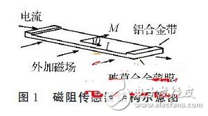
The magnetoresistance effect sensor is formed according to the magnetoresistance effect of the magnetic material. Figure 1 is a schematic diagram of the structure of a simple magnetoresistance effect sensor. Since the magnetic material (such as permalloy) has anisotropy, its magnetization is magnetized. The direction will depend on the easy axis of the material. The shape of the material and the direction of the magnetizing field. Therefore, in its linear range, the output voltage of the bridge is proportional to the measured magnetic field. At the same time, the magnetic flux in the three directions of XYZ is used to perform the trigonometric function. The transformation can know that the azimuth is the arctangent value above the X direction and the Y direction.
The triaxial gravity accelerometer is a polysilicon surface micromachined structure placed on top of the wafer. Due to the application of acceleration, the polysilicon spring is suspended above the structure of the wafer surface to provide strength resistance. The differential capacitor consists of an independent fixed plate and a movable mass connection plate. The structure deflection can be measured. The acceleration deflects the inertial mass. The differential capacitance is unbalanced, so that the amplitude of the sensor output is proportional to the acceleration. The phase sensitive demodulation is used to determine the amplitude and polarity of the acceleration.
Virtual reality positioning technology has developed rapidly at home and abroad, mainly in medical and entertainment achievements. The traditional domestic technology is mainly based on single-chip microcomputer as the core processor, and there are obvious deficiencies in data processing and transmission speed. The positioning system utilizes high-precision positioning sensors. The FPGA processes and transmits data to collect and process data in real time, reducing transmission pressure and improving data throughput and equipment utilization. Field programmable logic gate array FPGA is The mainstream ASIC device for modern IC design verification. FPGA is flexible in design, easy to modify, high in reliability, short in development cycle, fast in processing speed, easy to implement high-speed circuit design, easy to drive positioning sensor, and fast data Processing and transmission.
Data acquisition system overall design structure
This article uses Xilinx spartan3 series FPGA, ADI's ADXL345 three-axis gravity acceleration sensor and Honeywell's HMC5883L three-dimensional magnetoresistive sensor, using a modular structure to pipeline each unit separately. The whole system mainly includes: FPGA Core processing module. Hardware power module. Scene data processing module. Ethernet communication module. When the azimuth and tilt angle of the object change, the ADXL345 module and HMC5883L module will store the new data in the FIFO in the FPGA. It is uploaded to the host computer through UDP packet analysis and processing. The interface circuit in the system mainly has the interface of ADXL345 and FPGA. The interface between HMC5883L and FPGA. The interface circuit between Ethernet chip and FPGA. After the system is powered on, the FPGA sends out The signal includes two sensor clock drive signals, and the Ethernet chip controls the signal. The internal signal of the FPGA includes the FIFO control signal. The control signal transmitted by the sensor signal. The working process of the system is: the FPGA drives the sensors and Ethernet correctly. After that, the sensor starts sending data to the FPGA at a certain frequency. The FPGA stores the data in the FIFO immediately after receiving the data. At the same time, the FIFO stores the data once according to the write clock under the corresponding conditions, and sends the originally stored data to the Ethernet chip according to the clock; the Ethernet chip encapsulates the data. The UDP packet is uploaded to the host computer through the Ethernet bus. Finally, when the host computer receives valid data, it analyzes the data and transmits it to the 3D software part so that the objects in the 3D scene also have the same azimuth and The change of the tilt angle realizes the function of virtual reality.
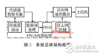
Data acquisition system modular design
3.1 HMC5883L data acquisition module design
The scene data module is the basic part of the whole measurement system and an indispensable module for the whole circuit operation. It includes the HMC5883L magnetoresistive sensor chip for measuring azimuth and the three-axis gravity acceleration sensor ADXL345 and HMC5883L for measuring the tilt angle. A surface mount high-integration module with a digital interface weak magnetic sensor chip for low-cost compass and magnetic field detection.
The HMC5883L's clock is a series of I2 C drive clock cycles. The design of this module is to drive the three-dimensional magnetoresistive sensor chip HMC5883L well and determine the data transfer order in the timing. Currently, the FPGA pin is used to control the corresponding timing. .
The data is collected in the fixed timing of the HMC5883L sensor. The collected data is a digital format with a specific format. It needs to be analyzed by certain algorithms and data to be sent to the host computer for operation. The communication between the FPGA and the HMC5883L uses I2C. The communication means uses the standard rate mode 100 kHz in the process of code writing. In the bus specification, the bit format of the bus is an 8-bit data/address transfer and a 1-bit acknowledge bit. The timing of the format shown in Figure 3 is shown. (Click to view larger image)

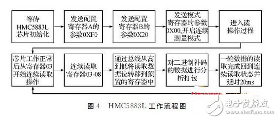
HMC5883L workflow: First, the chip is initialized for data waiting, then I2C transmission mode is used to control the data. A pre-test process needs corresponding measurement registers for corresponding configuration. First send the configuration register A configuration amount, For the write operation, the register instruction is the default value; the second step sends the configuration amount of the configuration register B, which is also the default value; the third step sends the configuration amount of the mode register, that is, the transmission data 0X00 (ie, the continuous measurement mode). The flow of the configured register has been completed. Then enter the read operation mode. At this time, according to the sampling speed of the clock, the internal register 03-08 of the sensor is operated cyclically to obtain data in three directions of X, Y, and Z, and read in The code is set in the register. The specific operation flow is shown in Figure 4.
3.2 ADXL345 data acquisition module design
The ADXL345 is used to measure the tilt angle in a virtual scene system. Its clock drive is also a series of I2 C drive clock cycles. The design of this module is also for the clock drive of the ADXL345 and the corresponding data read. The acquisition of register contents is the main content of the entire module.
In the actual scene system, the offset registers in the X, Y, and Z directions are mainly used to measure the measurement error of the original position in the measurement. For the data acquisition rate, the register OX2C is the CH0-CH3 of the register BW_RATE. Controlled. For the three-dimensional gravity acceleration sensor, the main initialization is also through the common I2 C bus to communicate with the FPGA, in the data acquisition, focus on the register data in the three gravity directions of X, Y, Z. The timing diagram is as follows As shown in Figure 5, the bus shared with the HMC5883L during the code writing process is controlled by the FPGA and belongs to the slave of the system control. Similarly, the 3D gravity acceleration sensor also needs to input the configuration of the initialization register according to the measurement requirements. Then it needs to be read. The register data bits are taken for bus reading, and stored in the configured 8-bit register, and then packaged and sent to the upper computer for data analysis. (Click to view larger image)

3.3 Scene data analysis
In the geomagnetic measurement process, the necessary analysis of the data is required to obtain the corresponding azimuth angle.
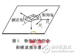
From the HMC5883L and ADX345 sensors, we can get the magnitude of the magnetic field of the earth's magnetic field on the three axes of space, Hx, Hy, Hz, and the acceleration sensor to measure the elevation angle φ and the roll angle θ.

In the formula, Ax, Ay, and Az are the acceleration values ​​measured in three directions of the gravity acceleration sensor. Under the calculation of a specific formula, the clockwise azimuth angle a of the current object can be roughly obtained.
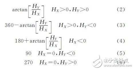
The above is a preliminary estimate of the azimuth parameters. The HMC5800L is also subject to external magnetic interference. The more prominent ones are the hard magnetic effect and the soft magnetic effect [8~9]. Generally speaking, for the hard magnetic effect, we The method adopted is to rotate the object 360° in the scene, and then obtain the maximum values ​​Xmax, Ymax, Zmax and minimum values ​​Xmin, Ymin, Zmin of the X, Y, Z coordinates after multiple sampling, and then for the hard magnetic effect Offset is

The hard magnetic effect only needs to use the data value of the test plus the offset value of off. For the soft magnetic effect, the compensation method is more complicated. Generally, the formula can be used for proper estimation. The project initially uses equation (12). Compensation. Where Xr is the true non-interfering coordinate value, a is its interference coefficient. Generally, soft magnetic interference requires a large amount of data to get the value of a. Generally, data can be taken at a specific angle, and then according to the data.

The actual value Xr and the corresponding non-interference value Xc are calculated, and the value of this coefficient of a can be obtained.
3.4 Ethernet communication module design
LAN8700 is an Ethernet physical layer chip of SMSC.
LAN8700 consists of encoder/decoder. Scrambler/descrambler. Waveform shaper. Output driver. Adaptive balanced twisted pair receiver. Clock data recovery function module.
The UDP_User_int module is defined in the FPGA module programming to implement the detailed process of data packing. In addition, the physical layer communication of the MAC is implemented by the MAC_top module, including PHY initialization, clock control, data generation control, MII interface control, and receive data control. The control of the registers, etc., all define the UDP_TOP top-level module to realize the smooth transmission of data between the FPGA and their interfaces. The RTL gate-level structure diagram implemented by the Ethernet driver module is shown in Figure 7.
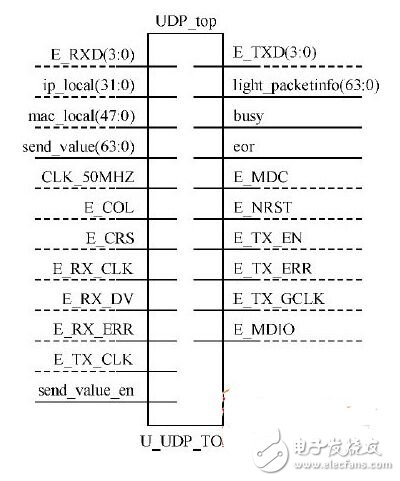
Where ip_local and mac_local are local IP and MAC addresses; each group of E_RXD and E_TXD is four 32-bit data, E_RXD is the data of the receiving MAC layer, E_TXD is the data sent to the MAC layer; each group of send_zb_value is 64 32-bit The data is packaged into a UDP packet, send_zb_value is a UDP packet sent to the Ethernet, and send_en is defined as an enable signal for transmitting data; E_COL and E_CRS are collision detection and carrier sense signals, respectively, and their role is to Controls the correct sending of UDP packets.
4 Conclusion
The HMC5883L chip is used in the design to measure the azimuth of the object. The auxiliary chip ADXL345 is used to determine the tilt angle and the object roll attitude, so that the actual situation of the object in the virtual scene is more accurate. The high-speed processing capability of the data by FPGA will be collected. The scene location content is quickly analyzed and processed and sent to the host computer in the local area network through the Ethernet control chip, and finally the virtual scene changes in the upper computer. The whole hardware system can work stably in the research and development project, and the work performance is good. Low energy consumption, the accuracy can reach within 1 ° range.
Overmolding the Connectors offers significant opportunities for cable improvements with higher pull strength and waterproof issue for those parts, which without these characteristic by conventional types.Such as jst jwpf connector. Just be free to contact us if you need any wire-harness solutions or partner for your products. Our professional and experienced team would support you by satisfied skill and service.
Molded Connectors,Molded Waterproof Connector,Molded Straight Wire Connector,Jst Jwpf Connector
ETOP WIREHARNESS LIMITED , https://www.etopwireharness.com