Improve phase array antenna test speed with high performance digital converter
Engineers originally used vector network analyzers (VNAs) to perform amplitude and phase measurements on the transmit/receive modules in phased array antennas. Recent improvements in manufacturing techniques have resulted in mass production of more flexible and more powerful transmit/receive modules.
However, the verification and characterization analysis creates a manufacturing bottleneck because the complete phased array antenna may contain an infinite number of T/R modules and multiple RF output channels from the array components. In the case of the amount of data that needs to be collected, it takes several days or weeks to verify the measured complex array. In order to shorten the test time, a completely different approach must be taken.
For cross-channel phase and amplitude measurements including transmit/receive modules, the Agilent M9703A's test system provides up to hundreds of simultaneous input channels for many simultaneous tests. At the same time, the Agilent M9703A provides the bandwidth required for digital conversion of signals such as pulse and chirp to meet future complex test needs.
Preface
Additional production test time increases manufacturing costs. In the case of active antenna arrays, a significant amount of production test time is spent on verification. While engineers face the pressure to reduce manufacturing costs, they also want to increase the flexibility of test systems to cover a wide range of use cases and ensure that their test platforms can test more efficiently with faster frequency switching performance and higher bandwidth. An array of energy.
This article briefly introduces important issues related to the use and selection of digitizers in phased array antenna test systems. In addition, it offers a solution to increase test speed with the modular Agilent AXIe M9703A (digital converter).
Important issues faced by phase array antenna test engineers
This article addresses the test challenges faced by phase array antenna engineers, including:
After down-conversion, the need for fast, wideband, and high-resolution sampling of the IF signal.
Phase coherent sampling is achieved on all input channels to provide relative amplitude and relative phase measurements.
Depending on the test scenario, there is a need for different trade-offs between sensitivity and analysis bandwidth.
First, the antenna signal enters the microwave mixer block, and the microwave/radio frequency of the antenna array is down-converted to IF within the 3 dB analog bandwidth of the digitizer. The choice of mixer block and local oscillator depends on the input frequency and acceptable conversion loss. The carrier frequency ranges from S to Ka band (2 to 40 GHz).
Second, the signal passes through several possible attenuation/gain and filter stages to take full advantage of the dynamic range and front-end characteristics of the digitizer.
Finally, the signal is sampled separately by a digitizer. If the required IF bandwidth is much narrower than the Nyquist (1.6 GSa/s) bandwidth of the 800 MHz, the digital down conversion (DDC) program can be used to tune the full bandwidth analog-to-digital conversion. The device outputs data to the desired narrower frequency analysis band. Using DDC reduces the overall noise power in the band, thereby increasing the signal-to-noise ratio (SNR).
If the noise power is random and evenly distributed throughout the spectrum, the noise power is reduced by:
10 x log (BWFin/BWInit).
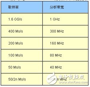
(Table 1) Sampling rate and bandwidth mode of the Agilent M9703A-DDC
Use the Agilent M9703A to increase calibration speed
Square Hole Breadboard,400 Tie Point Breadboard,Makeronics Breadboard,Small Solderless Breadboard
Cixi Zhongyi Electronics Factory , https://www.zybreadboard.com