Intelligent control neon circuit
RF cable can be customized for other specifications
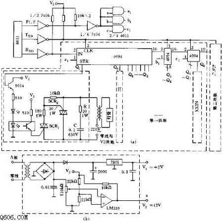
Circuit principle: The control circuit expands the input/output (I/0) port through the serial communication mode 0 of the 8031 ​​MCU, and the number of I/O is not limited. The first power driver board is formed by using three 4094 shift registers in series to obtain 24 I/O ports. If the number of I/O ports is insufficient, the second block, the third block, and the like can be constructed and connected in series.
The Rxd, Txd, and P1.7 of the 8031 ​​MCU realize level conversion through the 74LS06 open-collector OC gate and are connected to subsequent CMOS devices. The zero-crossing trigger signals a, b, and c generated by the zero-crossing signal generating circuits of the three-phase alternating current of A, B, and C are connected to the STR pins of three pieces of 4094 on each power driving board (a1, b1, c1) ), so that the load is triggered at the zero crossing of the AC voltage of each phase. The power drive unit circuit uses optical isolation to eliminate external interference and improve system reliability. The optocoupler output first drives the thyristor SCR1, and then the SCR1 drives the SCR2. The illuminating LED in the circuit is used for analog display during programming and debugging; the RC snubber circuit composed of the resistor-capacitor is used to absorb the neon light when the transformer is an inductive load. A large reverse surge current is generated to ensure smooth power drive.
The controller circuit is easy to expand, does not change the hardware circuit, and only needs to modify the data table arranged in the program memory and sent to the peripheral port 4094 for the user's request, and is generally easy to implement.
Dual Battery Manager,Smart Car Dual Battery Manager,Dual Battery Isolator,In-Vehicle Dual Battery Chargers
SUZHOU DEVELPOWER ENERGY EQUIPMENT CO.,LTD , https://www.fisoph-power.com