Make your own DTMF decoding digital display
The author made a DTMF digital display with reference to relevant information, and would like to share it with you.
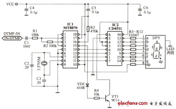
The circuit principle is shown in the drawing. DTMF digital decoder IC1 adopts MT8870, the 2 pin of the chip is the IN signal input end, the external crystal of 7 and 8 feet is used as the clock oscillation end, the frequency of the clock oscillation circuit is 3.579545MHz, and the generated double audio signal is the high frequency group. There are 16 kinds of combined frequencies from 1209 Hz to 1633 Hz and low frequency groups from 697 Hz to 941 Hz. After the two-input signal input by the 2-pin is digitally operated, the four-digit binary code ABCD is outputted at the data output terminals 11, 12, 13, and 14 and a positive pulse signal is output as the latter stage by the 15-pin at the end of the decoding. The latch pulse of the circuit.
CD4511 is a seven-segment BCD latch decoding, driving the common cathode digital tube display, CD4511 7, 5, 6 feet for ABCD code input, 3 feet LT for test light, 4 feet BI for blanking feet, 5 feet LE is the latch control terminal, and pins 9-15 are used to drive the digital tube to display characters. The output terminal uses the R5-R12 current limiting resistor to make the LED digital tube display 0-9 digits. The digital tube adopts the common cathode type, and the 15th pin of IC1 outputs a positive pulse signal, which is used as the latching pulse of the latter stage circuit, and the base of VD1, R4 to VT1, so that the collector outputs a low level signal. When the pin 8 of IC2 has a low level signal, it can drive the digital tube to display characters. The displayed characters are the numbers 0-9.
I have used this decoded digital display for more than half a year. With the frequency meter and oscilloscope, it is convenient to adjust the dual audio frequency when repairing the radio.

Wuxi Juxingyao Trading Co., Ltd , https://www.juxingyao.com