Smart home remote control system circuit design strategy - circuit diagram reading every day (172)
This system is a remote automatic control system for smart home environments based on infrared and GSM networks. The working principle is as follows: the user sends a command short message through his mobile phone, and the GSM module at home receives the command and sends it to the host (single-chip microcomputer). The host transmits the command to the corresponding extension (microcontroller) through infrared processing. After the extension processes the command, the corresponding device is started, the command given by the user is completed, and the response is replied to the host. After receiving the response, the host sends a reply short message through the GSM module to report the user completing the command. If the host does not receive the reply message of the extension within the specified time (here, timing 60s), the operation is considered invalid, and the reply operation invalid message is sent to the user's mobile phone, requesting the user to reissue the command. If the short message received is incorrect, the host will immediately reply to the user that the operation is invalid and request to reissue the command. The system structure is shown in Figure 1.
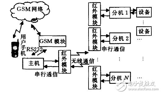
Figure 1 system composition diagram
MCU and GSM communication module
The MCU communicates with the GSM module through the RS232 serial communication interface, extracts the short message of the GSM device, transmits relevant information, and connects with the infrared module through the serial communication interface, and uses the infrared module to reach the communication between the main and the extension, therefore, Use AT89S52 chip. Two serial interfaces are required for control, but the 89S52 has only one serial port, so it is also necessary to perform analog serial interface communication in the program. The simplest external wiring circuit is shown in Figure 2.
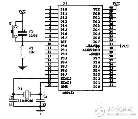
Figure 2 AT89S52 external wiring
The 89S52 communicates with the TC35 via an asynchronous serial interface with a communication rate of 9 600b/s, with 1 start bit, 8 data bits, 1 stop bit, and no parity. After the MCU starts, it issues an AT+CMGD-2 command to clear the data in the second storage space, and then continuously issues an instruction to read the second storage space. If there is data, it means that the data is received, and the data is processed. After the processing is completed, the spatial data is deleted. When the MCU sends a short message to the mobile phone, the MCU will issue a series of AT, AT+CMGF=0, AT+CMGS=X commands to the GSM module. After receiving the reply message, the content of the short message is finally sent.
Infrared wireless communication module
The infrared transmitter circuit includes a 38 kHz crystal oscillator, an inverter, a NAND gate, a driving gate Q1, and an infrared transmitting tube D1 as shown in FIG. The 38kHz crystal oscillator, resistor R3 and inverter form a pulse oscillator to generate a 38kHz pulse sequence as the carrier signal. The infrared emitter D1 uses the TSAL6238 produced by Vishay to emit an infrared beam of 950nm.
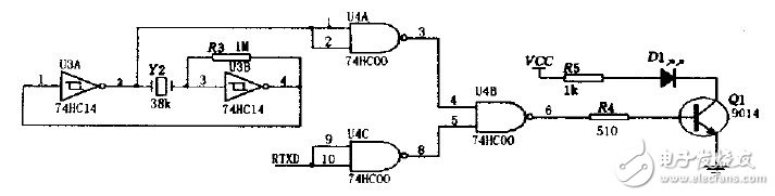
Figure 3 Infrared transmitter circuit diagram.
The infrared receiver circuit is shown in Figure 4. When the receiver receives the digit "O", the Q2 tube is turned on, so that RXD receives a low level. When the digit "1" is received, the Q2 tube is turned off and the RXD is received high. Level.
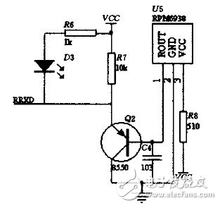
Figure 4 infrared receiver circuit diagram
Analog control
The system will perform different actions with different motors to simulate the response of the smart home to system control. As shown in Figure 5, when the MCU of the extension receives the address information of the machine, it extracts the data in the message. According to the command of the data, if the P0.0, P0.1 pins are set to low level, the others are high. Ping, then Q3, Q4 tube is turned on, the motor will rotate in the positive direction. If P0.2, P0.3 pin is set to low level, others are high level, then Q5, Q6 tube is turned on, the motor will be reversed. Rotation (the previous case was positive). If multiple motors are connected to one extension and there are multiple extensions, synchronous control of the various devices in the home can be realized in a smart home environment.
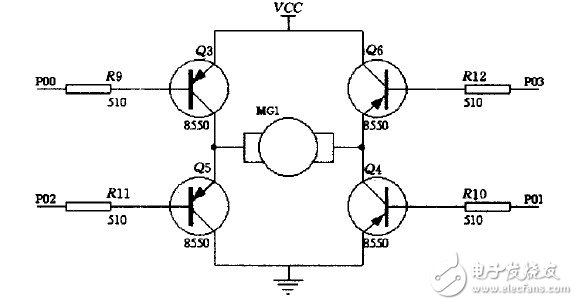
Figure 5 motor drive circuit
The system is safe and reliable with stable performance. At the same time, in addition to the remote automatic control of household equipment, the system can also be used for home communication, home security, and jointly set up a smart home control system.
Flexible Cables,Outdoor Flex Cable,Rubber Cable,Flexible Cable Wire
Shenzhen Bendakang Cables Holding Co., Ltd , https://www.bdkcables.com