A circular pole that uses Ansoft HFSS software to analyze the performance of the antenna...
Microstrip antennas have been widely used in various radio equipment due to their unique structure and diversified performance. Compared with commonly used microwave antennas, microstrip antennas have the advantages of small size, light weight, low profile, and conformal to carriers (such as aircraft). Among them, the circularly polarized microstrip antenna, because it can receive any polarized incoming wave, and the circularly polarized radiated wave generated by it can be received by any polarized antenna, so it has attracted more and more attention. The key to generating circularly polarized radiation waves with a microstrip antenna is to generate two linearly polarized waves with orthogonal polarization directions, equal amplitudes, and 90° phase difference.
This paper studies a circularly polarized slot microstrip antenna with a central slot, and uses Ansoft HFSS software to analyze the antenna performance, and designs an ultra-high frequency circularly polarized microstrip antenna.
1 Antenna theoretical analysis and design1.1 Circular polarization theory
According to the cavity mode theory, a single-chip microstrip antenna with a regular shape can be fed by a single point to produce two degenerate modes with orthogonal polarizations and equal amplitudes, but they cannot form a 90° phase difference. In order to form a 90° phase difference between the degenerate modes, it is necessary to add a degenerate mode separation unit to a regular-shaped monolithic microstrip antenna. When the size of the degenerate mode separation unit is selected appropriately, for the operating frequency, the equivalent impedance phase angle of one mode is advanced by 45°, and the equivalent impedance phase angle of the other mode is lagging by 45°, thus forming a circular polarization. radiation. Choosing the appropriate size and location of the mode separation unit and the appropriate feeding position are the main content of the design of this circularly polarized microstrip antenna.
As shown in Figure 1, Figure 1(a) shows the coordinate position of the rectangular microstrip antenna; Figure 1(b) shows the rectangular microstrip antenna with degenerate separation unit Δs, where the feed point is on the x-axis or y-axis The rectangular microstrip antenna is called Type A; the rectangular microstrip antenna with the feed point on the diagonal is called Type B.
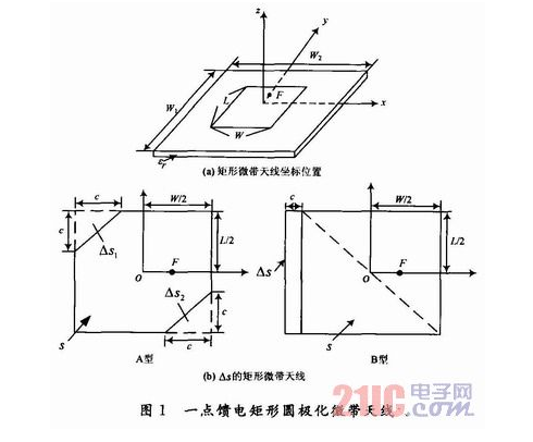
For the B-type one-point-fed rectangular circularly polarized microstrip antenna, the size of the degenerate separation unit â–³s that produces circular polarization is:
In the formula: s is the area of ​​the microstrip patch; Q0 is the overall quality factor of the antenna.
1.2 The design of the antenna
Use HFSS software to model the antenna, and the model is shown in Figure 2. The antenna uses air with a dielectric constant of approximately 1 as the substrate. At the same time, it is necessary to compromise the bandwidth and efficiency of the microstrip antenna, and finally choose the thickness of the medium as h=4 mm. Four slots of equal length are opened around the patch, which changes the current distribution on the surface of the patch, thereby increasing the equivalent length of the antenna, reducing the resonant frequency of the antenna, and achieving the purpose of reducing the size of the antenna. At the same time, the surface current excited by the antenna feed is concentrated in the center of the antenna patch due to the surface slotting, which is introduced at the center of the antenna patch at this time
A slot with a small size can realize the circular polarization performance of the antenna.
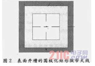
The width of the microstrip antenna slot has little effect on the resonant frequency, so the slot width of the antenna is 1 mm.
2 Simulation results2.1 Antenna parameter analysis
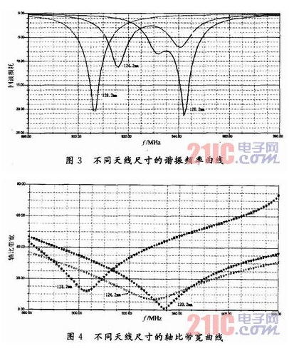
According to the antenna designed above, when the length of the microstrip patch is changed to 120.2 mm, 124.2 mm, and 128. 2 mm, the curves of resonance frequency and axial ratio bandwidth are shown in Figure 3 and Figure 4. Show. It can be seen from these two sets of curves that both the resonance frequency and the axial ratio bandwidth decrease with the increase of the antenna size, and have a certain influence on the minimum axial ratio.
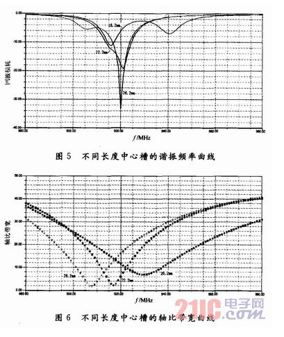
Keep the other parameters of the antenna unchanged, and change the size of the center slot to make it 18.2 mm, 22.2 mm, and 26.2 mm respectively, and the two sets of curves shown in Figure 5 and Figure 6 are obtained. It can be seen from Figure 5 that the slot length has a very small effect on the lowest resonant frequency, which is extremely conducive to the tuning of the antenna frequency. It can be seen from Figure 6 that as the length of the central groove increases, the minimum axis ratio shifts to the left.
2.2 Antenna simulation results
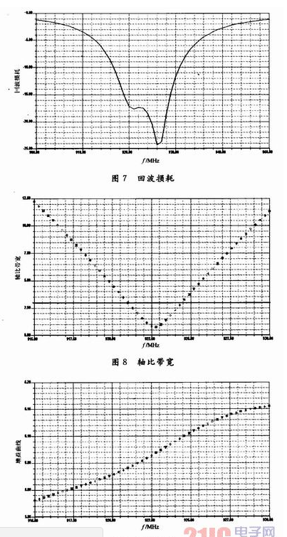
According to the design theory and numerical analysis of the microstrip antenna, after the optimization of HFSS, the size of the microstrip antenna is W=L=124.2 mm, the length of the side slot ls=36.5 mm, and the formula (1) can be used to obtain The length of the central groove is lp=22.8 mm. Make proper adjustments to the length and width of the center slot, and select an appropriate feeding position, and finally get an ideal circular polarization antenna. As shown in Figure 7-9, the center frequency of the antenna is 926 MHz, and the bandwidth reaches 14 dB. The minimum axial ratio reaches about 0.8, which realizes the circular polarization of the antenna in a wider frequency band.
Loading slots on the microstrip antenna can reduce the size of the antenna, but it will also reduce the bandwidth and efficiency of the antenna at the same time. This requires designers to compromise the contradiction between the two. The air with a small dielectric constant is used as the base of the microstrip antenna, which reduces the influence of the slot on the antenna bandwidth, and an antenna with relatively good performance is obtained.
Compared with large complex thin - wall castings, civil products have lower requirements on casting quality. However, for the latter, shorten the production cycle, improve the production efficiency of the problem becomes more prominent. The gelation process of common silica sol mainly depends on the dehydration and drying of silica sol, which takes longer time than the gelation of chemical hardening ethyl silicate. Ethyl silicate shell using ammonia dry each layer can be completed in 2h, and the final hardening of silica sol generally takes more than 12h, for some deep holes and other difficult to dry parts of the need for a longer time. At the same time, because the Investment Casting shell needs to be made in layers, each layer needs to be fully dried, to ensure that the lower shell immersion coating will not cause the problem of remelting off, and immersion coating itself, water will be immersed in the dried shell, resulting in a long overall drying cycle. It is a schematic diagram of the production cycle of silica sol shell investment casting under general conditions. As can be seen from the figure, shell making time accounts for more than 50% of the whole casting production cycle. To shorten the delivery time and shell making cycle is the core of the problem. The key factors to shorten the shell-making period can be divided into two aspects: internal cause and external cause. The main internal cause is the characteristics of the binder, and the external cause is the drying condition.
Silica Sol Casting industry in China is developing rapidly and its application is also very extensive.
Tianhui Machine Co.,Ltd , https://www.thcastings.com