A new way of using dielectric resonator array antenna to generate OAM beam
Abstract: Orbital Angular Momentum (OAM) technology provides a new modulation dimension for wireless communication systems and becomes an effective method to solve the problem of spectrum resource shortage. A novel OAM array antenna is proposed, which uses a dielectric resonator array antenna to generate OAM beams. The simulation results show that the radius of the OAM array antenna directly affects the effect of the OAM beam. At the same time, a suitable feeding position and feeding method can improve the central airspace problem and improve the long-distance transmission quality of the OAM beam to a certain extent. This OAM array antenna is small in size and has a wide selection of dielectric materials. It can solve the problems of high-frequency radiation element loss of loop OAM microstrip array antenna and large geometrical size in low-frequency band. It provides practical applications for OAM array antennas in the future wireless communication field. New reference value.
0 Preface
In recent years, the low utilization rate of spectrum resources has become an urgent bottleneck problem in the development of wireless communication technology. A variety of diversity technologies (such as space diversity, polarization diversity, frequency diversity, etc.) have been successfully used to transmit data to improve spectrum efficiency. . However, traditional modulation techniques only use resources such as frequency, time, code pattern, and space as degrees of freedom, and their modulation capabilities are limited. OAM vortex electromagnetic wave multiplexing technology can realize the simultaneous transmission of multiple signals at the same frequency point [1]. As a promising method, it provides certain solutions to the problems of low spectrum utilization and shortage of spectrum resources. Research ideas have brought immeasurable research value.
Orbital Angular Momentum (OAM) characterizes the natural properties of a spiral phase wavefront structure with a phase factor of exp(jlφ) [2]. OAM is introduced into wireless communication as a modulation dimension different from phase, amplitude, and polarization, which can effectively improve the capacity and efficiency of the communication system. Spiral lens [3], metasurface [4], spiral phase plate [5] and other optical field OAM beam generation methods are difficult to be applied to the microwave range of wireless communication systems. It is particularly important to explore suitable microwave range OAM beam generation methods. important. In 2013, TAMBURINI F and others conducted OAM wireless communication experiments based on spiral parabolic antennas [6], which proved the feasibility of using OAM vortex electromagnetic waves for wireless communication and increasing wireless transmission capacity; in 2014, BAI Q and others used 8 The same rectangular microstrip patch forms a circular phased array antenna to generate an OAM beam [7]; in 2015, BAI X et al. used a three-polarized round horn array antenna to generate an OAM beam [8]; in 2016, KANG MS et al. People use a circular array antenna equipped with 8-channel uniform power divider to generate an OAM beam with the number of modes l=1 [9]. Since then, more methods for OAM antennas and OAM beam generation have been proposed [10-11]. However, small size and high radiation efficiency are the main factors considered when using OAM array antennas. When the above-mentioned microstrip array antenna is used to generate OAM beams, since the radiating element is a microstrip patch, the antenna has a large geometric size in the low frequency band, which is not easy to achieve miniaturization; high frequency metal ohmic loss is high, and the radiation efficiency is low; and the spiral paraboloid The antenna structure is single and can only generate OAM beams with low-order mode numbers. In actual communication systems, its utilization value will be severely limited. Therefore, exploring a low-loss, small-volume, easy-to-process OAM array antenna is of great significance to the development of microwave communications in the future.
Dielectric resonator antennas are made of low-loss microwave dielectric materials. A suitable high dielectric constant can reduce the actual size of the antenna. There are also various feeding methods, which are more suitable for OAM array antennas. Based on the related theory of lossy loop antenna, this paper establishes the equivalent model of lossy loop dielectric resonator array antenna, and proposes a new way of using dielectric resonator array antenna to generate OAM beam. This OAM array antenna was simulated and optimized and related performance parameters were analyzed. The influence of different array radius on the effect of 3D far-field radiation pattern was analyzed. On this basis, the different feeding positions and different feeding of dielectric resonator array antennas were explored. The influence of the mode on the generation of the OAM beam.
1 Array antenna model and structure design
1.1 Equivalent model of lossy loop array antenna
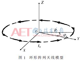
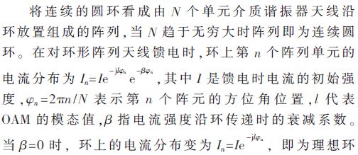
The ideal loop array antenna model cannot accurately describe the actual situation, because the loss of the loop array antenna is unavoidable, so the current intensity on the loop cannot always remain constant. Therefore, it is more reasonable to establish an equivalent model of a lossy loop array antenna to illustrate the principle of OAM beam generation. The loop array antenna model is shown in Figure 1.

1.2 Array antenna design
The side view and top view of the unit dielectric resonator antenna are shown in Figure 2. A rectangular coupling slot is opened on the ground plane, and the slot center coincides with the center of the radiating element. When the current is transmitted in the microstrip line, it is cut off by the rectangular slot, and the energy is coupled to the dielectric resonator antenna to generate radiation. The dielectric resonator antenna is placed vertically on the slot of the rectangular slot, and the microstrip line passes vertically through the center of the rectangular slot. Because the radiation impedance of the slot is the largest, more energy will be fed into the dielectric resonator antenna.
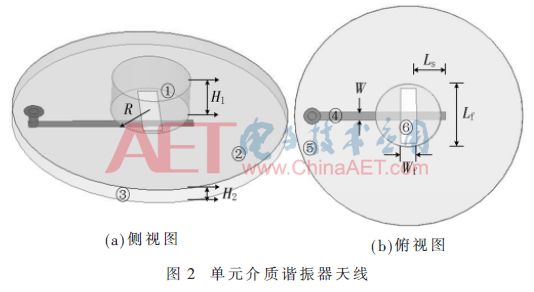
In Figure 2, ①represents the unit dielectric resonator antenna, which is made of ceramic-filled PTFE composite material, with a dielectric constant ε1=38.9, a bottom radius of R=2.86 mm, and a height of H1=2.51 mm; ② represents the connection Ground; ③ indicates that the material is a Rogers RT/duroid 5880 (tm) dielectric substrate, the thickness of the substrate is H2=1 mm, its relative permittivity ε2=2.65, and the loss tangent value is 0.02; ④ indicates the feeding microstrip line, Since the width of the 50 Ω microstrip line is about 2.4 mm, the width of the microstrip line will be too wide to affect the performance of the antenna, so the characteristic impedance is selected as 100 Ω, the width is W=0.72 mm, and the impedance matching transformation is performed to obtain 50 Ω impedance matching. The length LS of the microstrip line extending from the rectangular slot will directly affect the matching and return loss of the antenna. Through continuous simulation and optimization, it is finally found that the optimal effect can be achieved when LS=2.5 mm; ⑤ indicates the coaxial feed port; ⑥ indicates The length and width of the rectangular slot opened on the ground plane are Lf=5 mm and Wf=1.4 mm respectively. The change of the length and width of the rectangular slot will affect the impedance matching and gain characteristics of the antenna to a certain extent. When designing the slot size, the influence of slot length should be given priority. Because the slot length Lf has a major impact on the antenna, it not only affects the impedance matching and resonance frequency of the antenna, but also affects the antenna return loss. The slot width Wf has little effect on the resonance frequency and return loss, and mainly affects the impedance matching of the antenna.
2 Simulation and analysis
Figure 3(a) shows the return loss S11 of the array antenna, and the parameter reaches -32.73 dB at the center operating frequency of 10.5 GHz; Figure 3(b) shows the voltage standing wave ratio VSWR, and the array antenna reaches the center operating frequency of 10.5 GHz. 1.1, and the voltage standing wave ratio VSWR parameter is less than 1.5 near the center frequency, so this OAM array antenna has good impedance matching and the resonance frequency of each radiating element has good consistency, which meets the performance requirements of antenna design.
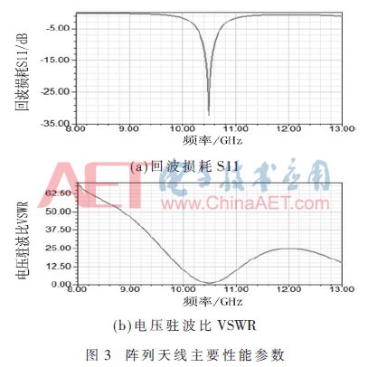
Figure 4 shows the far-field radiation pattern (λg is the wavelength in the medium) with modal values ​​l=1, 2, and 3 produced by different array radii. It can be found that as the modal value l increases, the central airspace gradually becomes larger; within a certain range, the larger the radius of the array, the better the effect of the OAM beam radiated by the dielectric resonator array antenna.
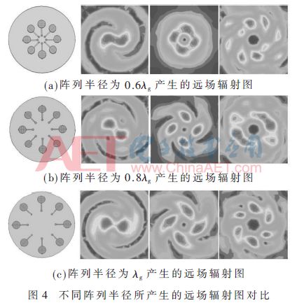
Figure 5 shows the far-field radiation pattern with modal values ​​of l=1, 2, and 3 generated by different feeding positions of the array radius. The comparison shows that when the feed is arranged according to the feeding position of Fig. 5(b), the central airspace is reduced, especially when the modal value l=3, the airspace is reduced more obviously. Figure 6 analyzes the changes in the gain pattern when the two feed positions in Figure 5 are arranged and fed, and the modal values ​​l=1 and 2 are selected to compare and find: Arrange the feed positions according to the way in Figure 5(b), and it radiates The total gain of each mode is stronger than the total gain of arranging the feeding positions in the manner shown in Figure 5(a). Therefore, when a dielectric resonator array antenna is used to generate OAM beams, choosing a suitable feeding position will help reduce the central airspace problem to a certain extent.
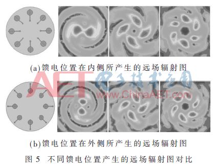

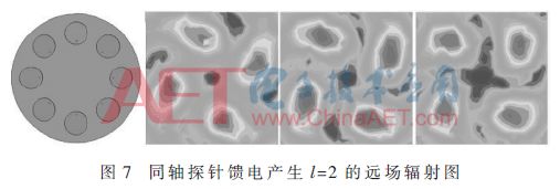
Comparing the case of (a) and (b) in Fig. 5 when the modal value l=2 is selected, it is found that when the OAM beam rotates, its central airspace is almost constant; if the coaxial probe in Fig. 7 is used When an OAM beam with a modal value of l=2 is generated by the feeding method, the central airspace will gradually expand and become more obvious when it is rotating and propagating. This leads to the radiation zero point in the main radiation direction of the OAM vortex electromagnetic wave during the propagation process. And with the increase of the communication distance, the phenomenon of energy diffusion occurs, which puts forward higher requirements for the reception of OAM vortex electromagnetic waves. Therefore, selecting a suitable feeding method can improve the receiving performance of the OAM antenna to a certain extent and solve the problem of long-distance high-quality transmission of OAM signals.
3 Conclusion
Based on the related theory of lossy loop antenna and its equivalent model, this paper proposes an OAM dielectric resonator array antenna. Through simulation optimization and analysis of the relevant performance parameters of the antenna, it is found that the radius of the array is within a certain range. The larger the radius, the better the far-field radiation pattern effect of this OAM antenna. At the same time, the far-field radiation pattern and gain of different feeding positions Analysis of the pattern shows that when using this OAM antenna to generate OAM vortex electromagnetic waves, a proper feeding position is helpful to solve the central airspace problem. On this basis, the modal value l=2 is used to explore the influence of OAM dielectric resonator array antennas on the OAM beam generated by different feeding methods. The results show that: when the coaxial probe is used to feed power, the transmission center The central airspace will gradually expand and the energy will spread. Therefore, a reasonable feeding method can improve the long-distance transmission quality of OAM beams to a certain extent, which is of great significance for accelerating the development of OAM antennas and applying them to actual wireless communication systems.
Toolkits For Cutting Mahine and Cutting Materials
It is suitable for the blade of the Screen Protector Cutting Machine and the tools for installing the Screen Protection Film.
If you want to learn more about Accesseries For Cutter,Screen Protector Cleaning Tool, Cutting Blade, Cell Phone Scraper Tool, Tool Kit, Cutting Head Parts please click "Product Details" to view Accesseries For Cutter,Screen Protector Cleaning Tool, Cutting Blade, Cell Phone Scraper Tool, Tool Kit, Cutting Head Parts parameters, models, pictures, prices and other information .
Whether you are a group or an individual, we will try our best to provide you with accurate and comprehensive information about Accesseries For Cutter,Screen Protector Cleaning Tool, Cutting Blade, Cell Phone Scraper Tool, Tool Kit, Cutting Head Parts!Accesseries For Cutter,Screen Protector Cleaning Tool, Cutting Blade, Cell Phone Scraper Tool, Tool Kit, Cutting Head Parts
Shenzhen Jianjiantong Technology Co., Ltd. , https://www.tpuscreenprotector.com