DVB-H mobile digital TV mobile phone design and its test plan
There are three types of mobile TVs, one based on analog TV broadcasting networks, the other based on mobile communication networks, and one based on digital broadcasting networks. The first solution is to add an analog TV module to the mobile phone to receive the analog TV broadcast program, which is not easy to be accepted by the consumer because the effect is not satisfactory. The scheme based on the mobile communication network is further divided into a unicast scheme based on a 2.5G mobile communication network and a multicast scheme based on a 3G mobile communication network. The unicast solution uses the 3GPP standard video format to provide on-demand, live broadcast, and carousel services through streaming media servers, such as China Mobile and China Unicom's WAP portal. The multicast scheme, such as MediaFLO of Qualcomm, USA, calculates the load of the mobile network, performs reasonable network scheduling, and controls the playing time and program transmission mode of the media program. Mobile TV based on digital TV broadcasting network has three major standards: DVB-H (Digital Video Broadcasting-Handheld) in Europe, ISDB-T (Integrated Services Digital Broadcasting-Terrestrial) in Japan, and T-DMB (Terrestrial-Digital Multimedia in Korea) Broadcasting). China's national standards have not yet been formally promulgated.
At present, T-DMB has been opened in South Korea and has more than 300,000 users. T-DMB experimental networks are already under construction in Beijing, Guangdong and Shanghai. DVB-H is also operating in several European countries. This article discusses the mobile TV solution based on digital TV broadcasting network mobile TV, TI's DM275, HOLLYWOOD DTV1OOx and TSC2110 mobile phone platform, this program is in the process of development.
Mobile digital TV mobile phone design
The mobile digital TV handset consists of two subsystems: the DVB-H mobile digital TV subsystem and the GSM/GPRS communication subsystem, as shown in Figure 1. The two subsystems are hosted on the application processor and control the DVB-H mobile digital TV receiver and GSM/GPRS communication module. 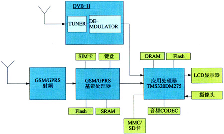
Figure 1 Mobile digital TV handset block diagram
Mobile digital television subsystem
The mobile digital television system consists of a mobile digital TV receiver including a tuner, a demodulator, and an application processor, as shown in FIG. 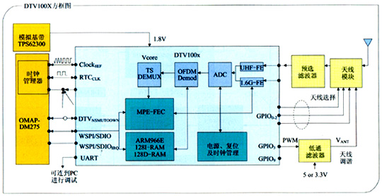
Figure 2 Functional block diagram of the digital TV module
The input to the mobile digital television receiver is a radio frequency broadcast signal from the antenna whose output is an MPEG-2 Transport Stream (TS) or IP data packet. They are then input to the application processor for decompression of video and audio and displayed on the LCD. Data communication between the mobile digital TV receiver and the application processor (TI DM275) is divided into two categories: (1) control and state exchange. The application processor downloads and configures the receiver startup program; the receiver reports the operation information and status of the application processor. (2) Data flow. The channel signal to be decoded is transmitted, including digital video, digital voice and data that are delivered from the receiver to the application processor. The above two types of data are transmitted on one physical interface or two physical interfaces. There are three physical interface modes, as listed in Table 1.
Table 1 Physical interface mode 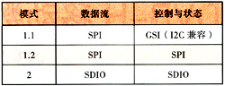
The SDIO interface mode of the receiver and the application processor is discussed below, as shown in Figure 3. 
Figure 3 Receiver with 4-bit data line SDIO interface
In SDIO interface mode, control and status reports and data streams are exchanged via SDIO and are divided into 4-bit and 1-bit data interface modes, as listed in Table 2.
Table 2 SDIO interface mode 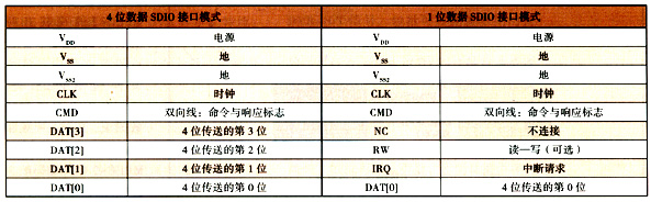
The integrated DSP core on the DM275 is the TMS320C54x and the CPU core is the ARM7TDMI. The DM275 is a portable terminal DSP that supports H.264/MPEG-4 AVC (hereafter referred to as H.264) codec processing, and is characterized by integrating a dedicated circuit responsible for MPEG-2 transport stream separation processing.
The DM275 is a successor to TI's TMS320DM270. It contains a 102MHz TMS320C54x DSP processor and a dual-core architecture of 88MHz ARM7TDMI microcontroller. A processing circuit for separating the MPEG-2 transport stream is added, and the dedicated circuit iMX responsible for the partial image data decoding process also supports the H.264 decoding process.
The codec processing capability of the DM275 is as follows: (1) Encoding processing. MPEG-4 Simple Profile: 640 × 480 pixels, 30 frames / s; MPEG-4 Advanced Simple Profile: 320 × 480 pixels, 30 frames / s. (2) Decoding processing. H.264: 352 × 288 pixels, 30 frames / s; MPEG-4 Advanced Simple Profile: 720 × 480 pixels, 30 frames / s; MPEG-2: 720 × 480 pixels, 30 frames / s; DivX: 720 × 480 Pixels, 30 frames/s; WMV (Windows Media Video) 9: 720 x 480 pixels, 30 frames/s.
The DM275 has a variety of external interfaces: USB, UART, MMC/SD, SPI, SDRAM, LCD. Can be directly with CCD or CMOS camera. Due to the flexible programming features and strong signal processing capabilities of the DM275, it can adapt to the needs of various mobile TV standards and is suitable for mobile TV multimedia mobile phone applications.
GSM/GPRS communication subsystem
The GSM/GPRS communication subsystem consists of radio frequency and baseband, and the baseband is composed of analog baseband and digital baseband. The baseband also controls peripheral circuits, including SIM cards, keyboards, flash memory, and SRAM. Power management, charge management, voice input and output, etc. are also controlled by baseband. This module is based on the TSC2110 platform of TEXAS INSTRUMENTS. TI's mobile phone platform is the most widely used mobile phone platform in the world. Beijing Shouxin Co., Ltd. has developed mobile phones on TI's mobile phone platform for more than 5 years and has rich experience in TI platform development. Therefore, the TSC2110 can be used to quickly integrate mobile digital TV handsets.
Connection between GSM/GPRS communication subsystem and mobile digital TV subsystem
The connection between the GSM/GPRS communication subsystem and the mobile digital TV subsystem is shown in Figure 4. The GSM/GPRS digital baseband and mobile digital TV application processor is passed through a 16-bit parallel data line and a 17-bit parallel address line. Connected. The DM275 operates in an external main processing mode, and the GSM/GPRS digital baseband accesses the DM275 through an external main CPU interface. The DM275 can operate in bypass mode to stop powering the DM275. The GSM/GPRS digital baseband can directly drive the LCD display to reduce standby power consumption. 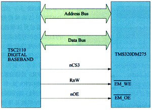
Figure 4 Connection diagram of GSM/GPRS communication subsystem and mobile digital TV subsystem
Mobile digital TV test solution
Testing of mobile digital TV handsets, including testing of GSM/GPRS communication functions and testing of DVB-H digital television functions. The test scheme for GSM/GPRS communication functions is very mature. Only the DVB-H TV function test is discussed here. MDTV testing includes job verification and performance verification. Work verification refers to the complete reception of signals under ideal conditions; performance verification refers to the signal reception capability at the DVB-H terminal.
Basic requirements for DVB-H/T work verification
(1) Broadcasting of DVB-H/T signals for one TV program; (2) Full MPE FEC; (3) Time SLICING; (4) Support for PSI/SI; (5) Operation in UHF band. For performance verification, VHF and L-band and insertion attenuation are also required.
DVB-H/T work verification simple device
In a simple device for DVB-H/T operation verification, all data is recorded in a computer and transmitted to a modulator that provides radio frequency signals. This device can evaluate DVB-H/T reception independently of the content being transmitted. Device. The device is shown in Figure 5. 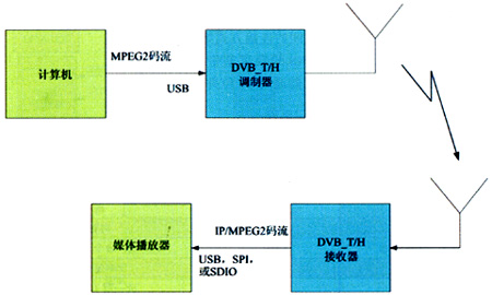
Figure 5 DVB-H/T work verification simple device
The laptop stores the recorded data stream and sends it to the modulator via USB. There are two types of recorded data streams: (1) data streams recorded for DVB-T. The video audio stream in MPEG-2 format is encapsulated into an MPEG-2 transport stream file, which contains the PSI/SI table. (2) The data stream recorded for DVB-H. The H.264 video and AAC audio formats are encapsulated into MPEG-2 transport stream files, which also contain PSI/SI tables.
The DVB-T/H radio frequency modulator converts the DVB asynchronous bit stream into a radio frequency signal, which performs the following functions: upconversion, modulation, and overall control of the entire DVB-H/T physical layer parameters. Enensys' NN6-1161 modulator is recommended.
The evaluated DVB-H/T receiver is connected to a computer or embedded platform via USB or SDIO. The computer serves two purposes: receiving multimedia streams and playing them; diagnostic retrieval and monitoring of DVB-H/T receivers. A package installed on your computer can play content and retrieve diagnostics. The software package also allows the user to monitor and control the following parameters: RF tuner parameters (frequency, gain, etc.); demodulator control parameters (eg FFT mode, guard interval, etc.); DVB-H/T connection layer (MPE-FEC) parameters (such as BURST size, time slice length, etc.).
Advanced device for DVB-H/T work verification
The advanced device for DVB-H/T work verification is shown in Figure 6. The laptop stores the recorded data stream and outputs it via a network connection. The data stream is recorded in H.264 format and sent via RTP/UDP. The IP packetizer (IPE) converts the IP stream into a DVB asynchronous bit stream. Perform the following tasks: multi-protocol packet, section wrapper, time slice, PSI/SI insert. The IP packetizer recommends the DataPlanet DP14502. 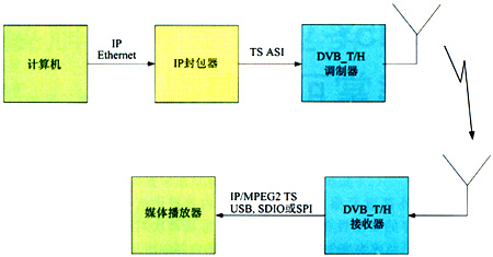
Figure 6 DVB-H/T work verification advanced device
The DVB-T/H radio frequency modulator converts the DVB asynchronous bit stream into a radio frequency signal, which performs the following functions: upconversion, modulation, and overall control of the entire DVB-H/T physical layer parameters. Enensys' NN6-1161 modulator is recommended.
DVB-H/T performance verification device
This device uses the R&S broadcast test system SFU, as shown in Figure 7. This device can also be used as an advanced platform for controlling channel parameters directly related to the air interface, such as output level, attenuation, RF frequency sweep, fading effects, additive noise, and the like. 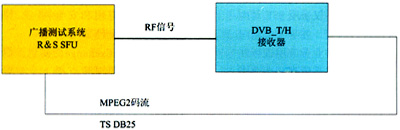
Figure 7 DVB-H/T performance verification device
R&S's broadcast test system provides complete DVB-H/T signals, including the ability to configure different broadcast modes and modulation parameters. The RF signal output by the test system can be directly input to the DVB-H receiver or transmitted to the air. The transport stream output from the DVB-H receiver is sent back to the broadcast test system to compare the transmitted and received data to obtain DVB-H receiver performance under intermediate conditions. This device is mainly used to measure the quality of decoded signals under channel attenuation conditions, that is, to provide a means of evaluating and verifying the performance of a DVB-H receiver.
This article refers to the address: http://
Micro inverter is a small inverter used in solar power generation systems, its main function is to convert the direct current generated by a single Solar Panel into alternating current. Unlike traditional centralized inverters, microinverters are usually equipped with one per solar panel, that is, each solar panel has an independent microinverter.
Main effect:
1. Individual control: The microinverter provides independent conversion control for each solar panel, which means that each solar panel can optimize its power output individually. This maximizes the power generation efficiency of the solar panels since shading or other influences only affect the power generation efficiency of individual panels, not the entire array.
2. Reliability: Since each solar panel is equipped with a micro-inverter, even if one of the inverters fails, the other panels can still work normally, thereby improving the reliability of the entire system.
3. Flexible installation: Micro-inverters are usually small and can be installed near solar panels without being concentrated in one location, so installation is more flexible and convenient.
Differences from other inverters:
1. Individual control: Compared with traditional centralized inverters, microinverters provide independent conversion control for each solar panel, enabling each panel to reach its maximum power output.
2. Fault isolation: The micro-inverter has the function of fault isolation. Even if one of the inverters fails, other panels can continue to work without affecting the operation of the entire system.
3. Installation method: The micro-inverter can be flexibly installed near the solar panel, and does not need to be concentrated in one location, so the installation is more flexible and convenient.
4. Applicable scale: micro-inverters are usually used in small-scale solar power generation systems, while traditional centralized inverters are suitable for larger-scale photovoltaic power plants.
Overall, the main role of microinverters is to individually control and optimize the power generation efficiency of solar panels and improve the reliability of the system. Compared with traditional centralized inverters, it has some advantages in terms of flexibility, fault isolation and applicable scale.
grid tie micro inverter, off grid solar micro inverter, hoymiles microinverter price, micro inverter solar system, solar system with micro inverters
Ningbo Autrends International Trade Co., Ltd. , https://www.aitsolarpanels.com