High-IF sampling receiver front-end with integrated bandpass filter
Circuit function and advantage
The circuit in Figure 1 is based on the ADL5565 ultralow noise differential amplifier driver and the narrow-band receiver front end of the AD9642 14-bit, 250 MSPS analog-to-digital converter (ADC).
The third-order Butterworth anti-aliasing filter is optimized based on the performance and interface requirements of the amplifier and ADC. The total insertion loss due to the filter network and other components is only 5.8 dB.
The overall circuit bandwidth is 18 MHz and the passband flatness is 3 dB. With a 127MHz analog input, the measured signal-to-noise ratio (SNR) and spurious-free dynamic range (SFDR) are 71.7dBFS and 92 dBc, respectively. The sampling frequency is 205 MSPS, so the IF input signal is located in the second Nyquist zone between 102.5 MHz and 205 MHz.
Circuit description
The circuit accepts a single-ended input and converts it to a differential signal using a wide-bandwidth (3 GHz) Mini-Circuits TC2-1T 1:2 transformer. The 6 GHz differential amplifier ADL5565 operates with a gain of 6 dB with a differential input impedance of 200 Ω and a differential input impedance of 100 Ω with a gain of 12 dB. It also offers a gain option of 15.5 dB.
The ADL5565 is the ideal driver for the AD9642, which provides a fully differential architecture in the ADC with a bandpass filter that provides good high frequency common-mode rejection while minimizing second-order distortion products. The ADL5565 provides 6dB or 12dB of gain depending on the input connection. This circuit uses a gain of 12dB to compensate for the insertion loss of the filter network and transformer (approximately 5.8dB) with a total signal gain of 5.5dB.
Figure 1. 14-bit, 250 MSPS wideband receiver front end (schematic diagram: all connections and decoupling not shown) Gain, loss, and signal levels measured at 127 MHz input frequency
The 1.5 dBm input signal produces a 1.75 V pp full-scale differential signal at the ADC input.
The anti-aliasing filter is a third-order Butterworth filter designed using a standard filter design procedure. The Butterworth filter was chosen because of its passband flatness. The third-order filter produces an AC noise bandwidth-to-noise ratio of 1.05 and can be designed with a variety of free filter programs, such as Nuhertz Technologies Filter Free or Quite Universal Circuit Simulator (Qucs) Free SimulaTIon.
For best performance, the ADL5565 should load a net differential load of 200 Ω. The 15 Ω series resistor isolates the filter capacitor from the amplifier output. The 100Ω resistor is connected in parallel with the downstream impedance and produces a net load impedance of 217Ω when added to a 30 Ω series resistor.
A 5Ω resistor in series with the ADC input isolates the internal switching transients from the filter and amplifier.
The 2.85kΩ input impedance is determined by a spreadsheet that can be downloaded from the AD9642 web page. Simply use the parallel tracking mode value when the target IF frequency is centered. The spreadsheet gives both real and imaginary values.
The third-order Butterworth filter is designed with a source impedance (differential) of 200Ω, a load impedance (differential) of 200Ω, a center frequency of 127MHz, and a 3dB bandwidth of 20MHz. The values ​​calculated by the standard filter design program are shown in Figure 1. Due to the large series inductance required, the inductance of 1.59 μH is reduced to 620 nH, and the capacitance of 0.987 pF is scaled up to 2.53 pF, so the resonant frequency of 127 MHz is kept constant, making the component values ​​more realistic.
Figure 2. Start of the design of a third-order differential Butterworth filter, ZS = 200 Ω, ZL = 200 Ω, FC = 127 MHz, BW = 20 MHz
The value of the second shunt capacitor is subtracted from the 2.5 pF internal capacitance of the ADC to give a value of 37.3 pF. In this circuit, the capacitor is located near the ADC to reduce/absorb charge backlash.
The value selected for the final filter passive component (adjusted by actual circuit parasitics) is shown in Figure 1. Table 1 summarizes the measurement performance of the system with a 3 dB bandwidth of 18 MHz centered at 127 MHz. The total insertion loss of the network is approximately 5.8 dB. Figure 3 shows the frequency response; Figure 4 shows the SNR and SFDR performance.
Table 1. Measurement performance of the circuit
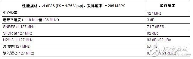
Figure 3. Passband flatness performance versus frequency
Figure 4. SNR/SFDR performance vs. frequency, sample rate = 205 MSPS
Figure 5. General Differential Amplifier/ADC Interface with Bandpass Filter
VGA Cable, VGA to VGA HD15 Monitor Cable SVGA M/M HD Cable Gold Plated Connectors Support 1080P Full HD for PC, HD TV, Projector, etc
Product Features
The VGA cable is widely used in VGA digital transmission mode connection, adapted to a variety of electronic devices 15PIN interface, such as computers, high definition DVD and computer monitors, projectors, high definition digital TV, rear projection, plasma TVs and other appliances Device cable.
Compatible with the resolution
VGA cable can automatically identify the resolution required to adjust the device to support 800 * 600/1024 * 768/1152 * 864/1280720/1280 * 768/1280 * 800/1280 * 9601280 * 1024/1360 * 768/1600 * 1200/1920 * 1080
Connectivity - VGA to VGA Cable Connector HD15 Male to Male.
[15-pin MALE VGA CABLE] Screw-in VGA cable with 15-pin male input and output for gaming, video editing and video projection.
[HIGH PERFORMANCE] Supports resolutions at 800x600 (SVGA), 1024x768 (XGA), 1600x1200 (UXGA), 1080p (Full HD), 1920x1200 (WUXGA), and up for high resolution LCD and LED monitors.
[FUNCTIONS] Links VGA-equipped computer to any display with 15-pin VGA port also known as RGB, DE-15, HD-15, DB-15, D-sub 15 and HDB-15, input and output.
[FERRITE CORES] The VGA to VGA cable equipped with ferrite cores that could minimize crosstalk, avoid electrical radiation interference and protect against electromagnetic interference (EMI) and radio frequency interference (RFI).
[SECURITY] The VGA cord engineered with molded strain relief connectors for durability, grip treads for easy plugging and unplugging, and finger-tightened screws for a secure connection.
Compute Cable,Notebook Cable,HDMI to VGA Cord,VGA Cable,HDMI Cable
UCOAX , https://www.ucoax.com