Industrial networking technology using PROFIBUS standard
Industrial networking technology using PROFIBUS standard
Industrial communication in process automation, factory automation or motion control is achieved through fieldbus technology. Fieldbus refers to an industrial communication system that uses a series of media, such as copper cables, optical fibers, or wireless links, and uses bit serial transmission technology to convert distributed field devices (sensors, actuators, drives, and transmitters, etc.) ) Coupling to a central control system or management system.
In the past ten years, PROFIBUS has become the leader in the global fieldbus technology market. While providing field-level horizontal communication, it can also provide vertical communication through several levels. Hierarchical and coordinated industrial communication systems [for example: PROFIBUS with both a low-level AS interface connection and a high-level Ethernet connection (via PROFInet)] can provide ideal prerequisites for clear networking in all aspects of the production process (See Figure 1).
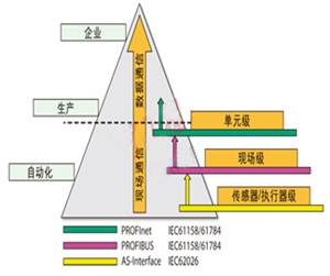
Figure 1 Communication diagram in automatic control technology
Sensor-actuator level communication: Binary sensor and actuator signals are transmitted through the sensor actuator bus, thereby providing a low-cost and easy-to-use technology in which data and power can be transmitted through a shared medium.
Field-level communication: Distributed equipment (such as I / O modules, transmitters, drives, analysis equipment, and tubes or operator terminals) communicate through a powerful real-time communication system and automatic control system.
Optoelectronics level communication: Programmable controllers (such as PLC and PC) not only communicate with each other, but also communicate with IT systems in office applications using standards such as Ethernet, TCP / IP, intranet, and Internet.
PROFIBUS and other fieldbus systems have been established in 1999 as an international standard-IEC 61158. The second part of the standard (IEC 61158-2) defines several transmission technologies, of which RS-485 is one of the most commonly used technologies in PROFIBUS.
The compatibility of the PROFIBUS standard depends on the specific application. Several components used in this design will affect the overall compatibility. One of the components is the RS-485 transceiver. When selecting a transceiver, you must understand the physical layer and understand the role of the transceiver in the physical layer.
Selection of PROFIBUS transceiver
Two key features distinguish PROFIBUS from standard RS-485 transceivers. The first feature is the differential output VOD of the drive, and it is very suitable for PROFIBUS DP applications. The second feature is the differential output capacitance that is part of the total station capacitance, thus limiting the maximum signaling rate specified by IEC 61158-2.
Differential output voltage (VOD)
RS-485 defines VOD as the differential output voltage across a 60-Ω resistor in the common-mode voltage range of –7V to 12V (see Figure 2). The PROFIBUS DP master-slave communication protocol test specification requires that the peak-to-peak differential output voltage VOD (PP) should be between 4V and 7V. Most product specifications do not specify the peak-to-peak value, but specify the minimum zero-to-peak voltage VOD = ± 2.1V, which is 4.2 VPP.
Figure 2 Comparison of RS-485 bus transceiver with a certain load and PROFIBUS transceiver with the same load
Apply VOD definitions to PROFIBUS loads
The equivalent circuit on the left in Figure 2 shows an RS-485 bus with a 32-unit load, while the circuit on the right shows a PROFIBUS network with the same unit load. The change of the equivalent circuit is caused by the additional requirements of the PROFIBUS standard, which requires that a pull-up resistor and a pull-down resistor be provided at each end of the bus to maintain the differential voltage when a bus is idle.
High VOD provides greater noise margin
The 5V termination voltage brings a positive shift in VOD, which brings an asymmetric waveform to the receiver input. This asymmetry causes distortion of the duty cycle at the output of the receiver. The degree of duty cycle distortion depends on the number of signal rises and falls and the input threshold of the receiver. Since most PROFIBUS applications are in a noisy industrial environment, asymmetry also means that the noise tolerance of one logic state is lower than the noise tolerance of another logic state of particular concern. Ultimately, the driver must overcome this offset to meet the requirements of the PROFIBUS DP test criteria, which requires that the bus voltage amplitude change not exceed 0.5V.
For the above reasons, the minimum VOD value specified by the PROFIBUS driver should be greater than the typical value in RS-485 applications.
Reflection and Vcc changes bring greater VOD
The PROFIBUS standard defines the specifications of type A cables (see Table 100 of IEC 61158-2), which will be used for 220Ω bus termination. Because the impedance value of this unique cable can vary from 135Ω to 165Ω (in the 20MHz bandwidth range), and the equivalent differential terminal impedance at the end of the cable is 171Ω, the reflection and power supply voltage due to impedance mismatch The changes will cause VOD to exceed the limit level specified in the PROFIBUS DP test guidelines shown in Table 1.
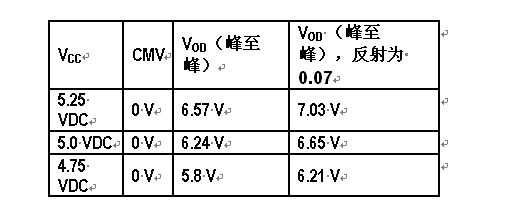
Table 1 VOD changes with Vcc
Therefore, in order to ensure the compatibility of the standard, we strongly recommend to limit Vcc to 5V and choose a cable with a characteristic impedance close to 165Ω.
The PROFIBUS standards EN 50170 and IEC61158-2 specify the maximum bus capacitance for a specific signaling rate. The higher the bus capacitance, the lower the signaling rate. For example, at a signaling rate of 500 kbps, the total capacitance of all bus nodes does not exceed 600 pF, while at a signaling rate of 12 Mbps, the maximum allowed capacitance is 200 pF. The bus capacitance includes all the connectors, stubs, and differential capacitance of the device on the bus, but does not include the cable capacitance. Since the change in bus capacitance is mainly caused by the change in device capacitance, on the ideal level, the product specification of the PROFIBUS transceiver should specify the maximum output capacitance to allow accurate prediction of the maximum possible signaling rate. So far, the only transceiver that can ensure a maximum output capacitance of 10 pF is the SN65HVD1176.
Key stability
Robustness depends on the ability of the transceiver to handle electrical overstress (EOS). Specific forms of this electrical overstress include electrostatic discharge (ESD), transient voltage, and common-mode voltage. The difference between these robust measurement methods is the peak voltage and its duration, while the small peak voltage and the long duration determine the maximum absolute rating (AMR). Electrostatic discharge (ESD) ratings mean high peak voltage and short test pulses. The transient voltage will drop between the ESD and AMR ratings.
Maximum Absolute Rating (AMR) / Recommended Operating Conditions (ROC)
The AMR of the bus pins refers to the maximum amplitude of the low-frequency sine wave that can be used but does not cause damage. The recommended operating conditions are a subset of AMR. Since most PROFIBUS transceivers are based on RS-485 technology, the ROC of its bus I / O conforms to the RS-485 standard from –7V to + 12V. Although AMR will vary from manufacturer to manufacturer, the voltage range specified in ROC will usually vary by 2V.
Common mode voltage range and suppression
Just as the maximum absolute rating limits the recommended operating conditions, ROC also limits the common-mode voltage range of the receiver. In applications where the driver and receiver are operating at different ground potentials, a wide common-mode voltage range is very important. Because in this case, the ground potential difference will increase the common-mode voltage on the bus, and at the same time, the PROFIBUS transceiver must be able to withstand the changes in the common-mode voltage of the receiver input signal.
Another robustness indicator is the common mode rejection ratio (CMR). A high CMR (that is, 4 V) indicates that even when there is a large common-mode voltage change in amplitude and rise time, the communication performance of the transceiver can still be ensured to be accurate.
ESD protection
ESD events are usually measured in terms of voltage magnitude (kV) and rise time (ns). ESD testing is defined in JEDEC Standard 22 of test method A114-A. This special standard defines the human body model (HBM).
In order to make the network able to withstand such transient phenomena with large impact, this requires the transceiver to have an internal protection diode that can react quickly to high voltages. Figure 3 shows the equivalent schematics of the A output and the B output, which specifically indicates that the ESD protection circuit is turned on when the voltage exceeds 16V. In addition, it should be noted that the 16V and 16 kV ESD ratings of the transceiver shown in Figure 3 are different from the maximum absolute ratings of the device.
Figure 3 SN65HVD1176 equivalent output schematic
Transient overvoltage protection
The transient overvoltage is defined in the TIA / EIA-485 standard. The standard stipulates its definition and requirements. For the strong current interruption caused by the twisted pair, the transient phenomenon that may occur on the line should be protected transiently. This duration is much longer than ESD events (microseconds to nanoseconds), while the voltage level is greatly reduced (± 25V vs. kV). The specification also requires a test voltage of ± 25V, and a powerful transceiver (for example: SN65HVD1176) can withstand a transient overvoltage of ± 40V.
The overstress conditions mentioned so far do not represent all possible overstress conditions that devices in the industrial environment may face, but these overstress conditions mentioned do provide a qualitative measurement method for the robustness of the device.
The greater the maximum absolute rating, transient overvoltage protection, and ESD rating, the more robust the interface.
in conclusion
PROFIBUS is specifically designed for industrial applications and therefore requires a robust interface. Refer to the maximum absolute ratings of the transceiver bus pins, transient overvoltage protection, and ESD ratings for robustness measurement standards. Compared with other PROFIBUS transceivers, SN65HVD1176 is more robust. The device also has a lower bus capacitance (up to 10 pf) to meet the capacitance requirements for higher speed applications described in IEC 61158-2.
What`s your impression for Intel I3 Laptop? You can take i3 Laptop Deals as the entry level of Gaming Laptop . There are different parameters standards,like 14 Inch Laptop I3 11th Generation, 14inch 256GB Intel I5 11th Generation Laptop, 14.1 inch Intel i7 11th Generation Laptop, 15.6 inch I3 10th Generation Laptop,15 inch Intel I5 10th Generation Laptop, 15inch Intel i7 11th Generation Laptop, etc. That`s some of Top 10 Gaming Laptops. To operating OS, more than 80% clients choose windows 10, home or pro option; nowadays windows 11 is new arrival, you can choose as your demand. Rich slots meet your different potential application scenarios, home, office, public places, academic situations, etc.
Dual storage channels, support HDD and SSD. Your customers can update in future according potential demands.
Of course, other type, like yoga notebook, 2 In 1 Laptop , Android Tablet, Custom All In One PC , 14 inch Student Laptop, i7 16gb ram 4gb graphics laptop, etc. available here also. Just call us and get right details quickly.
Intel I3 Laptop,Laptop I3 11th Generation,i3 10th Generation Laptop,i3 Laptop Deals,Laptop Intel Core I3 Gen 11
Henan Shuyi Electronics Co., Ltd. , https://www.shuyiaiopc.com