Introduction to P(1dB) Characteristics of the MAX2116 Satellite Tuner
Tag: MAX2116 satellite tuner
This article refers to the address: http://
Abstract: This article provides the P1dB data measured by the MAX2116 in the actual combination of RF and baseband. The MAX2116/MAX2118 family of low-cost direct conversion tuner ICs are designed for applications such as digital direct broadcast satellite (DBS) television, professional VSAT systems, and two-way Internet satellite communications. The MAX2116/MAX2118 use a wideband I/Q downconverter to convert the L-band signal directly to a baseband signal. Operating frequencies range from 925MHz to 2175MHz.
Introduction
The MAX2116 P1db data is measured over a specific combination of these two gains within the adjustable range of RF and baseband gain. These data can be used to select gain control settings to properly distribute front-end and back-end gains to achieve proper P1db performance. P1db and noise figure data together are useful for optimizing the dynamic range of the receiver system.
For large received signals, high P1db is required to avoid tuner saturation. Turning the RF variable gain amplifier to low gain, P1db will be greatly increased for large signal reception. Since the reduction in RF gain increases the noise figure of the tuner, the system design requires careful balancing of P1db and noise figure. This application note is a way to help you find the balance.
Application overview
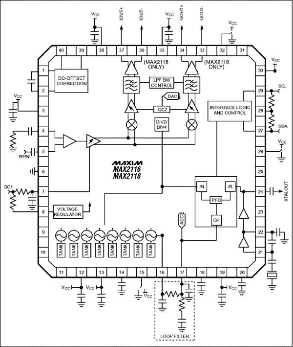
Figure 1 shows a typical application circuit for the MAX2116/MAX2118. Pins 4 and 5 are differential RF inputs. At high input signal levels, the output amplifier will define the carrier-to-noise ratio (C/N), one of which is P1db. . At low input signal levels, the system noise figure will define the tuner's carrier-to-noise ratio (C/N).

Figure 1. Typical Application Circuit for the MAX2116/MAX2118
Pin 7 (GC1) is the variable gain control of the RF front end. The gain control line is typically controlled by a filtered PWM signal generated by a baseband demodulator IC. In a closed loop system, this filtered PWM output makes the I/Q output of the MAX2116 a constant amplitude signal.
The MAX2116's 37 and 34 pins are I/Q outputs. The gain of the single-ended output amplifier can be set to provide an output of 800mVP-P.
There is a variable gain baseband amplifier behind the mixer. The gain of this amplifier can be set by register GC2. GC2 is adjustable from 0 to 31 (decimal). System P1db can be set by a specific combination of GC1 and GC2.

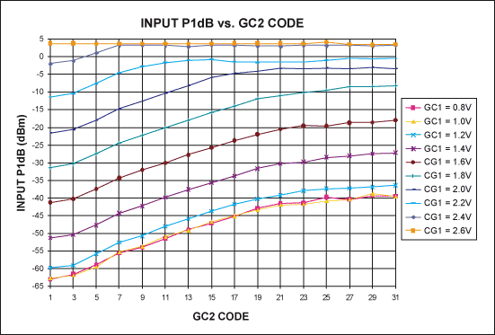
Figure 2. MAX2116 input P1db and GC2 codes
Figure 2 shows the P1db of the MAX2116 at different RF and baseband gains. As the front-end and back-end gains decrease, the trend of P1db growth is obvious, which is mainly the impact of the front-end. When the current gain is set to a minimum (2.6V), P1db reaches its upper limit of approximately +3.5dB, regardless of the GC2 setting. The data in Figure 2 is measured with a 1550MHz tone RF input and a 5MHz IF signal.

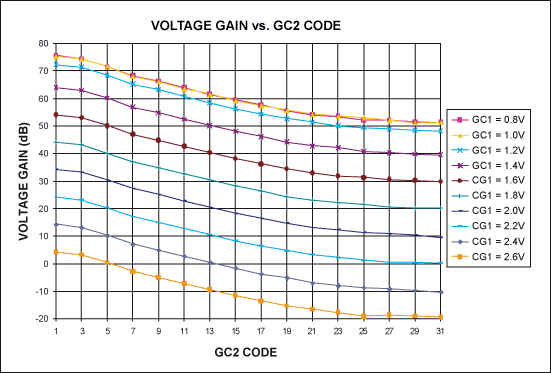
Figure 3. MAX2116 voltage gain and GC2 code
Figure 3 shows the voltage gain of the MAX2116 at different gain control settings. These gain control settings correspond to the settings in Figure 2. Its maximum gain is 76dB, the dynamic range of GC1 is 72dB, and the dynamic range of GC2 is 22dB. These data are very close to the values ​​given in the manual.
in conclusion
This article presents the P1db data for the MAX2116 in its RF and baseband gain control settings. These data are useful for determining the possible RF and baseband gain assignments to achieve proper P1db performance.
SC/PC Fiber Optic Fast Connector
Sc/Pc Fiber Optic Fast Connector,Fast Fiber Connector Kit,Quick Connect Fiber Connectors,Sc Quick Connector
Ningbo Fengwei Communication Technology Co., Ltd , https://www.fengweifiberoptic.com