Production of solar controller based on PWM technology
The solar power generation system uses solar panels (PV panels) to absorb the solar light energy and convert it into electric energy, charge it to the storage battery, and then output DC low-voltage electricity (usually a small system is 12V or 24V), or it becomes 220V through the inverter. Regular electric power is used to realize the environmental protection and energy saving scheme for utilizing the solar energy to the electrical appliances.
The core component of solar power generation is a solar controller. Its performance and design level directly affect the efficiency and cost performance of the system, even the working life and maintenance cost, especially the battery life.
The solar garden light is composed of solar panels, controllers, batteries, 12V light source, and some parts of the electrical components, together with the light poles, lampshades, lamp holders, solar panel brackets and other hardware parts, see the right picture. The battery is a large proportion of the investment cost in the system. The control must not allow the battery to be overcharged or overdischarged under any circumstances, otherwise the life will be greatly shortened.
Currently, solar panels are about 23% more efficient. It can protect the overcharge and overdischarge of the battery. This is the main task of the solar controller.
First, solar garden light solar controller function
Battery reverse connection protection is “+â€, “-†pole reverse protection; solar battery reverse connection protection; load overcurrent and short circuit, surge impact protection; battery open circuit protection such as battery open circuit, controller cuts off load to ensure load is not Damage; overcharge, overvoltage protection; battery type can choose ordinary lead acid or colloidal lead acid; battery over discharge protection; soft output start, prevent battery voltage drop during the load access, false protection; line lightning protection, lightning protection From the solar panel and lead into the burning controller; light control, time control or light / time mixed control switch, programmable selection; various status display is charging, charging state, load state; PWM charging method, floating charging function is superior; Night anti-reverse discharge protection; PWM ambient temperature compensation; full electronic switch, effectively extending controller life and reducing operating current loss.
Second, the technical parameters (according to the ambient temperature of 25 ° C) see attached table

Third, the type of solar controller
Using a single-chip microcomputer can make the charging work simple and efficient. The line selection does not select parallel type, because short circuit of the PV board output end will affect the service life of the PV board when fully charged. Therefore, it is better to use tandem type. The single-chip PWM system has the maximum power point tracking capability of photovoltaics. The utilization rate of photovoltaic cells is high. When the PWM makes the battery tend to be full, the frequency and time of the pulse are shortened. The change of the average charging current during the charging process is more in line with the state of charge of the battery. 0 to 100% charging work.
The charging of the battery by the solar PV panel is divided into three stages: direct charging, floating charging and trickle charging. When designing the circuit, it is necessary to perform temperature correction compensation for the charging and discharging voltage set point of the battery, that is, the voltage setting value of each charging and discharging phase is automatically adjusted according to the temperature change. The temperature compensation should meet the technical conditions of the battery, and the single section takes 4mV/°C as the reference value.
Most battery manufacturers recommend that batteries (not required for gel batteries) require occasional overcharging. This is going to be equalized charging every two months. After the normal charging is completed for one hour, directly charge, the maximum voltage is 16V, then stop charging for one hour, then equalize the charging, repeat 2 to 3 times to complete the equalization charging process.
Fourth, the controller
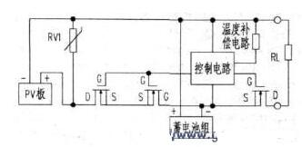
The controller is used for solar garden lights, with a load of 50W or less, and 5A current is sufficient for system design. The controller is composed of a charging circuit, a discharging circuit, a state indicating circuit, and a temperature compensation circuit.
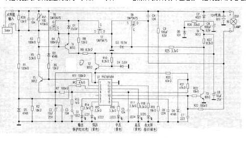
Battery BTl is a 12V34Ah ​​fully sealed battery, which is the main power supply of the controller. Capacitors C1, C3, and C4 are high-frequency filter capacitors that filter out unwanted high-frequency clutter generated by the PV panel and the load, reducing interference with the microcontroller and system. The varistor RVl absorbs the flash voltage of the lightning entering the controller through the PV panel and the leads. Components such as T4 and D6 stabilize the voltage input to the 12V battery by about 10V to prevent the influence of battery voltage changes on the system. T2, D4 regulator 5V supply to the microcontroller and individual components. D1 and D3 are MOS tube gate protection elements. R1, R2, R12, R28, and D5 form a solar PV panel voltage detection circuit, which reflects the various states of the PV panel input to the single-chip U1, and also acts as an automatic switch light to the garden light. R19, ​​R24, C6 form the battery voltage detection circuit, which reflects the state of the battery from the voltage at both ends of the battery, and then is processed by the single-chip software to make the corresponding charging phase control. The 1 pin of the single chip of the U1 is the positive power pin, and the 10 pin is the ground wire of the controller, that is, the negative end of the battery. The 4-pin is a lead-acid liquid battery and a gel battery. The function foot is selected by the S4 switch to ensure that the battery is a colloidal structure. T3 is the transistor for controlling the load output. When it is turned on, the MOS output control tube T is turned off, so that the load RL has no power, and the output protection LED1 is lit.
T Copper Tube Terminals,Non-Insulated Pin-Shaped Naked Terminal,Copper Cable Lugs Terminals,Insulated Fork Cable Spade Terminal
Taixing Longyi Terminals Co.,Ltd. , https://www.lycopperlugs.com