The use of MAX4090 and reconstruction filter
Abstract: In most video applications, the video signal generated by the DAC needs to be smoothed and filtered by the reconstruction filter to eliminate aliasing noise caused by sampling. The MAX4090 is a DC-coupled output driver that can drive video signals after reconstruction filters. The video DAC can drive loads between 75Ω and 300Ω. Due to the low input impedance (<100Ω) of the MAX4090 during normal operation, special attention is required when using the reconstruction filter in the front end of the MAX4090.
For standard video signals, the video passband is approximately 6MHz, and the system oversampling frequency is 27MHz. A 9W BW low-pass filter (LPF) is usually used as the reconstruction filter. The following discusses how to construct simple 2nd and 3rd order passive Butterworth low-pass filters with a cutoff frequency of 9MHz, and discusses the use of these filters with the MAX4090 (Figures 1 and 4).
Realization of the second-order Butterworth low-pass filter Table 1 shows the nominal value of a 2nd-order Butterworth low-pass filter at 1 rad / s, and the source / load impedance is 1 Ω.
Table 1.
According to the following formula, L and C can be calculated when the cutoff frequency is 9MHz. Table 2 gives approximate L, C values, and -3dB bandwidth and attenuation at 27MHz. It can effectively attenuate the aliasing noise caused by sampling. The attenuation at the frequency of 27MHz is 20dB. The MAX4090 requires low input impedance stability, and the input impedance cannot be reactive. If R1 / R2 is greater than 100Ω, a resistor RIS (Figure 1) of 20Ω to 100Ω should be connected in series between the filter and the input capacitor (C4) to avoid oscillation.

Table 2.
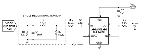
figure 1.
Figure 2 shows the frequency response when R1 = R2 = 150Ω. At 6MHz, the attenuation is 1.4dB; at 27MHz, the attenuation is about 20dB. Figure 3 shows the multi-burst response when R1 = R2 = 150Ω.
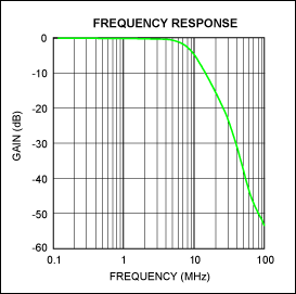
Figure 2. Frequency response
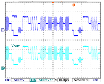
Figure 3. Multi-group response
3rd order Butterworth low-pass filter implementation If you need a flatter passband and greater stopband attenuation, you can use a 3rd order LPF.
Table 3 shows the normalized parameters of a 3rd order Butterworth low-pass filter, 1rad / s cutoff frequency and 3rad / s stop band frequency. Table 4 shows the L and C values ​​under different source / load impedance conditions and the -3dB bandwidth and attenuation at 27MHz. The attenuation exceeds 27dB at 27MHz. When R1 = R2 = 150Ω, the attenuation at 6MHz is 0.6dB (Figure 5).
table 3.
Table 4.
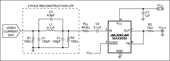
Figure 4.
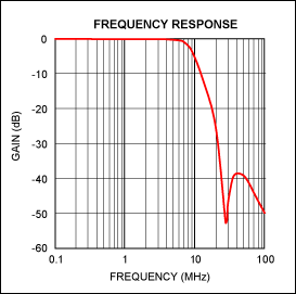
Figure 5.
Sag correction In 5V applications, the MAX4090 can use Sag configuration to meet AC-coupled video output requirements. Sag correction refers to compensating the effect of a high-pass filter composed of a 150Ω load and output capacitor on low frequencies. In video applications, the cut-off frequency of the high-pass filter must be low enough to ensure that the field sync signal is passed to avoid field tilt. The cut-off frequency must be below 3Hz to 5Hz, and the coupling capacitance is usually> 220µF. The MAX4090 uses two 22µF capacitors instead of large-size coupling capacitors (Figure 6). Tests have shown that even if the output coupling capacitor C5 is greater than 47µF, it will not improve the circuit performance. When the power supply voltage is lower than 4.5V, it is not recommended to use the Sag correction of the MAX4090.
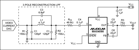
Image 6.
For standard video signals, the video passband is approximately 6MHz, and the system oversampling frequency is 27MHz. A 9W BW low-pass filter (LPF) is usually used as the reconstruction filter. The following discusses how to construct simple 2nd and 3rd order passive Butterworth low-pass filters with a cutoff frequency of 9MHz, and discusses the use of these filters with the MAX4090 (Figures 1 and 4).
Realization of the second-order Butterworth low-pass filter Table 1 shows the nominal value of a 2nd-order Butterworth low-pass filter at 1 rad / s, and the source / load impedance is 1 Ω.
Table 1.
| Rn1 = Rn2 (Ω) | Cn1 (F) | Ln1 (H) |
| 1 | 1.414 | 1.414 |
According to the following formula, L and C can be calculated when the cutoff frequency is 9MHz. Table 2 gives approximate L, C values, and -3dB bandwidth and attenuation at 27MHz. It can effectively attenuate the aliasing noise caused by sampling. The attenuation at the frequency of 27MHz is 20dB. The MAX4090 requires low input impedance stability, and the input impedance cannot be reactive. If R1 / R2 is greater than 100Ω, a resistor RIS (Figure 1) of 20Ω to 100Ω should be connected in series between the filter and the input capacitor (C4) to avoid oscillation.

Table 2.
| R1 = R2 (Ω) | C1 (pF) | L1 (µH) | RIS (Ω) | 3dB BW (MHz) | AttenuaTIon at 27MHz (dB) |
| 75 | 330 | 1.8 | 0 | 8.7 | 20 |
| 150 | 150 | 3.9 | 50 | 9 | 20 |
| 200 | 120 | 4.7 | 50 | 9.3 | twenty two |
| 300 | 82 | 8.2 | 100 | 8.7 | 20 |

figure 1.
Figure 2 shows the frequency response when R1 = R2 = 150Ω. At 6MHz, the attenuation is 1.4dB; at 27MHz, the attenuation is about 20dB. Figure 3 shows the multi-burst response when R1 = R2 = 150Ω.

Figure 2. Frequency response

Figure 3. Multi-group response
3rd order Butterworth low-pass filter implementation If you need a flatter passband and greater stopband attenuation, you can use a 3rd order LPF.
Table 3 shows the normalized parameters of a 3rd order Butterworth low-pass filter, 1rad / s cutoff frequency and 3rad / s stop band frequency. Table 4 shows the L and C values ​​under different source / load impedance conditions and the -3dB bandwidth and attenuation at 27MHz. The attenuation exceeds 27dB at 27MHz. When R1 = R2 = 150Ω, the attenuation at 6MHz is 0.6dB (Figure 5).
table 3.
| Rn1 = Rn2 (Ω) | Cn1 (F) | Cn2 (F) | Cn3 (F) | Ln1 (H) |
| 1 | 0.923 | 0.923 | 0.06 | 1.846 |
Table 4.
| R1 = R2 (Ω) | C1 (pF) | C2 (pF) | C3 (pF) | L (µH) | RIS (Ω) | 3dB BW (MHz) | AttenuaTIon at 27MHz (dB) |
| 75 | 220 | 220 | 15 | 2.2 | 0 | 9.3 | 43 |
| 150 | 120 | 120 | 6.8 | 4.7 | 50 | 8.9 | 50 |
| 300 | 56 | 56 | 3.3 | 10 | 100 | 9 | 45 |

Figure 4.

Figure 5.
Sag correction In 5V applications, the MAX4090 can use Sag configuration to meet AC-coupled video output requirements. Sag correction refers to compensating the effect of a high-pass filter composed of a 150Ω load and output capacitor on low frequencies. In video applications, the cut-off frequency of the high-pass filter must be low enough to ensure that the field sync signal is passed to avoid field tilt. The cut-off frequency must be below 3Hz to 5Hz, and the coupling capacitance is usually> 220µF. The MAX4090 uses two 22µF capacitors instead of large-size coupling capacitors (Figure 6). Tests have shown that even if the output coupling capacitor C5 is greater than 47µF, it will not improve the circuit performance. When the power supply voltage is lower than 4.5V, it is not recommended to use the Sag correction of the MAX4090.

Image 6.
Auto Switches Panels,Marine Switch Pane,Usb Car Charger,Digital Voltmeter Display
Dongguan Andu Electronic Co., Ltd. , https://www.idofuse.com