Conductive circuit inspection and maintenance
I. Management regulations
According to the Q/GDW 168-2008 "Transmission and Transformation State Inspection and Repair Test Regulations", when the infrared thermal image detection is abnormal, the previous measurement result is too large or shows a significant growth trend, and there is no measurement for 2 years since the last time. After the measurement has been performed more than 100 times, the closing operation, and the disassembly of the core component or body, the main loop resistance should be measured.
Second, the principle of loop resistance tester

    The current source is supplied to the Rx current of the measured resistance via the "I+, I-" two ports (also called the I-type port). The magnitude of the current is read by the ammeter I, and the voltage drop across the Rx is "U+, U-". Also referred to as a V-shaped port, it is taken out and read out from the voltmeter V. By measuring I and U, the resistance of the measured resistance can be calculated.
Third, the operation method
    (1) Contact the operator on duty to temporarily disconnect the grounding knife or grounding wire at the end of the isolating switch and close the isolating switch.
    (2) Wiring according to the wiring method shown in Figure 3-7-2.

    (3) The connection between the instrument panel and the test line should be tight and there should be no looseness.
    (4) It should be wired according to the four-terminal method, that is, the current line should be clamped on the outside of the test object, and the voltage line should be clamped inside the test object. The current and voltage must be the same polarity.
    (5) After checking and confirming that it is correct, pick up 220V AC, close the power switch, and the instrument enters the power on state.
    (6) Adjust the “Current Selection†knob, select the current gear to be selected, and then press the “Measure†button. At this time, the resistance meter display value is the measured loop resistance value.
    (7) After the measurement is completed, disconnect the power switch and collect the test clamp.
Fourth, matters needing attention
    (1) Read the instructions carefully before using the instrument.
    (2) Please wire according to the correct wiring method in the manual.
    (3) The instrument shall not test the loop resistance in the live loop.
    (4) The instrument must be reliably grounded during use.
    (5) When the instrument is not in use, it should be stored in a ventilated, dry, cool, clean place, paying attention to moisture and corrosion-proof gases.
V. Analysis and processing of test results
    (1) Main circuit resistance value (manufacturer's specified value (note value).
    (2) When there is a deviation in value, it is generally caused by the following reasons:
        1) Contact form: point contact, line contact, face contact.
        2) Contact surface condition: When the contact surface forms an oxide film (except for silver), the oxide film is much larger than the metal itself.
        3) Contact pressure.
        4) The roughness of the contact surface.
    (3) Treatment: Remove the oxide layer of the static and dynamic contacts, clean the moving and static contacts, apply conductive paste, and tighten the bolts.
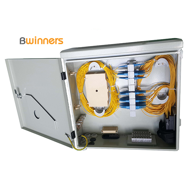
Indoor Fiber Optical Distribution Box(Metal)
Fiber Optical Distribution Box(Metal) Fiber Optic Distribution Box is specially designed for FTTH or FTTB for Indoor/Outdoor application. It is can manage single,ribbon & bundle fiber cables. It consists of splicing, distribution and panel with ensures the excess fiber cords and pigtails in good order, no interval and easy for management and operation. It offers mufti-functions of distribution management.

Indoor Fiber Optical Distribution Box(Metal),Fiber Optic Distribution Cabinet,Metal Electrical Boxes,Metal Equipment Cabinet
Sijee Optical Communication Technology Co.,Ltd , https://www.sijee-optical.com