Circuit filtering principle
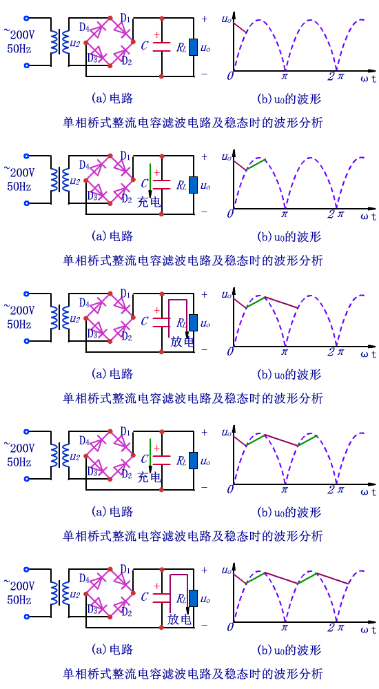
The filter capacitor has a large capacity, so electrolytic capacitors are generally used. When wiring, pay attention to the positive and negative electrodes of the electrolytic capacitor. The capacitor filter circuit utilizes the charging and discharging functions of the capacitor to make the output voltage tend to be smooth.
★ When u2 is positive half cycle and the value is greater than the voltage uC across the capacitor, diodes D1 and D3 are turned on, D2 and D4 are turned off, current flows through load resistor RL, and capacitor C is charged in the other. When uC>u2, the D1 and D3 tubes are reverse biased and turned off, and the capacitor is discharged through the load resistor RL, and the uC slowly decreases exponentially.

★When u2 is negative half-cycle amplitude changes just above uC, D2 and D4 become conductive due to the forward voltage, u2 charges C again, uC rises to the peak of u2 and then starts to fall; drops to a certain value When D2 and D4 become cutoff, C discharges to RL, and uC decreases exponentially; when discharge reaches a certain value, D1 and D3 become conductive, and the above process is repeated.
Influence of RL and C on charge and discharge
The charging time constant of the capacitor is rDC. Because the rD of the diode is small, the charging time constant is small and the charging speed is fast;
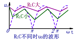
RLC is the discharge time constant. Because RL is large, the discharge time constant is much larger than the charge time constant. Therefore, the filtering effect depends on the discharge time constant.
The larger the capacitance C, the larger the load resistance RL, the smoother the output voltage after filtering, and the larger the average value, as shown in the figure.

The function of the filter capacitor is simply to make the output voltage after the filter a stable DC voltage. The working principle is that the capacitor is charged when the rectified voltage is higher than the capacitor voltage, and the capacitor is discharged when the rectified voltage is lower than the capacitor voltage. To make the output voltage basically stable.
The filter capacitor has a large capacity, so electrolytic capacitors are generally used. When wiring, pay attention to the positive and negative electrodes of the electrolytic capacitor. The capacitor filter circuit utilizes the charging and discharging functions of the capacitor to make the output voltage tend to be smooth.
★ When u2 is positive half cycle and the value is greater than the voltage uC across the capacitor, diodes D1 and D3 are turned on, D2 and D4 are turned off, current flows through load resistor RL, and capacitor C is charged in the other. When uC>u2, the D1 and D3 tubes are reverse biased and turned off, and the capacitor is discharged through the load resistor RL, and the uC slowly decreases exponentially.

★When u2 is negative half-cycle amplitude changes just above uC, D2 and D4 become conductive due to the forward voltage, u2 charges C again, uC rises to the peak of u2 and then starts to fall; drops to a certain value When D2 and D4 become cutoff, C discharges to RL, and uC decreases exponentially; when discharge reaches a certain value, D1 and D3 become conductive, and the above process is repeated.
Influence of RL and C on charge and discharge
The charging time constant of the capacitor is rDC. Because the rD of the diode is small, the charging time constant is small and the charging speed is fast;
RLC is the discharge time constant. Because RL is large, the discharge time constant is much larger than the charge time constant. Therefore, the filtering effect depends on the discharge time constant.
The larger the capacitance C, the larger the load resistance RL, the smoother the output voltage after filtering, and the larger the average value, as shown in the figure.

The rectifying circuit is a circuit that converts alternating current into direct current, but the pulsating component of the direct current output is large, and the pulsation coefficient of the DC power required by the general electronic equipment is less than 0.01. Therefore, the voltage of the rectified output must take certain measures. Try to reduce the ripple component in the output voltage. At the same time, try to save the DC component in the output voltage so that the output voltage is close to the ideal DC power. Such a circuit is a filter circuit in the DC power supply.
Commonly used filter circuits are passive filtering and active filtering. The main forms of passive filtering are capacitive filtering, inductive filtering and complex filtering (including inverted L-type, LC filtering, LCÏ€-type filtering and RCÏ€-type filtering, etc.). The main form of active filtering is active RC filtering, also known as electronic filters.
The magnitude of the pulsating component in the direct current is represented by a pulsation coefficient. The larger the value, the worse the filtering effect of the filter.
Pulsation coefficient (S) = fundamental maximum of output voltage AC component / DC component of output voltage
The pulsation coefficient of the half-wave rectified output voltage is S=1.57, and the ripple coefficient of the output voltage of the full-wave rectification and bridge rectification is S≈O.67. For the full-wave and bridge rectifier circuits, the C-type filter circuit is used, and its ripple coefficient is S=1/(4(RLC/T-1). (T is the period of the DC ripple voltage of the rectified output.)
The RC-Ï€ type filter circuit is essentially composed of a RC filter circuit based on the capacitor filter. As shown in Figure 1
The box is the added primary RC filter circuit. If S' is used to indicate the pulsation coefficient of the voltage across C1, the pulsation coefficient S=(1/ωC2R')S' at both ends of the output voltage.
It can be seen from the analysis that the larger the R is, the larger the C2 is, the smaller the pulsation coefficient is, that is, the better the filtering effect is. When the R value increases, the DC voltage drop across the resistor increases, which increases the internal loss of the DC power supply; if the C2 capacitance is increased, the capacitor's volume and weight are increased, and the implementation is not realized. reality.
In order to solve this contradiction, an active filter circuit, also called an electronic filter, is often used. The circuit is shown in Figure 2. It is a circuit formed by connecting a π-type RC filter circuit composed of C1, R, and C2 and an emitter device composed of an active device-transistor T. As can be seen from Fig. 2, the current flowing through R is IR = IE / (1 + β) = IRL / (1 + β). The current flowing through the resistor R is only 1/(1+β) of the load current. Therefore, a larger R can be used, which is matched with C2 to obtain a better filtering effect, so that the pulsating component of the voltage across C2 is reduced. The output voltage is substantially equal to the voltage across C2, so the ripple component of the output voltage is also reduced.
From the two ends of the RL load resistor, the filter elements R and C2 of the base circuit are folded into the emitter circuit, which is equivalent to a decrease of (1+β) times and a C2 increase by (1+β) times. The required capacitance C2 is only 1/β of the capacitance required for a general RCπ type filter, such as a DC amplification factor of the transistor β=50. If a general RCπ type filter is required, the capacitance capacity is 1000 μF, such as using an electronic filter. Then the capacitor only needs 20μF to meet the requirements. This circuit can be used to select the larger resistors and smaller capacitors to achieve the same filtering effect, so it is widely used in the power supply of some small electronic devices.

The utility model provides a disposable electronic cigarette, comprising: a hollow shell, the bottom of the shell is provided with a lower cover; the shell contains an atomizer, and the outer side of the atomizer is sheathed with a disposable cigarette A bomb, a microphone cover is arranged under the atomizer, a microphone is covered under the microphone cover, a battery is arranged on one side of the atomizer, and an upper cover is arranged on the top of the casing; The atomizer includes an atomizing core, an oil-absorbing cotton sleeved on the outside of the atomizing core, and an atomizer outer tube sleeved on the outside of the oil-absorbing cotton. The disposable electronic cigarette provided by the utility model absorbs the smoke oil on the surface through the absorbing cotton, and then atomizes the smoke through the atomizing core, which greatly reduces the risk of oil leakage, at the same time, reduces the burning of cotton and ensures the smoking taste.The utility model provides a disposable electronic cigarette, comprising: a hollow shell, the bottom of the shell is provided with a lower cover; the shell contains an atomizer, and the outer side of the atomizer is sheathed with a disposable cigarette A bomb, a microphone cover is arranged under the atomizer, a microphone is covered under the microphone cover, a battery is arranged on one side of the atomizer, and an upper cover is arranged on the top of the casing; The atomizer includes an atomizing core, an oil-absorbing cotton sleeved on the outside of the atomizing core, and an atomizer outer tube sleeved on the outside of the oil-absorbing cotton. The disposable electronic cigarette provided by the utility model absorbs the smoke oil on the surface through the absorbing cotton, and then atomizes the smoke through the atomizing core, which greatly reduces the risk of oil leakage, at the same time, reduces the burning of cotton and ensures the smoking taste.The utility model provides a disposable electronic cigarette, comprising: a hollow shell, the bottom of the shell is provided with a lower cover; the shell contains an atomizer, and the outer side of the atomizer is sheathed with a disposable cigarette A bomb, a microphone cover is arranged under the atomizer, a microphone is covered under the microphone cover, a battery is arranged on one side of the atomizer, and an upper cover is arranged on the top of the casing; The atomizer includes an atomizing core, an oil-absorbing cotton sleeved on the outside of the atomizing core, and an atomizer outer tube sleeved on the outside of the oil-absorbing cotton. The disposable electronic cigarette provided by the utility model absorbs the smoke oil on the surface through the absorbing cotton, and then atomizes the smoke through the atomizing core, which greatly reduces the risk of oil leakage, at the same time, reduces the burning of cotton and ensures the smoking taste.
maskking vape,maskking vape price,maskking vape review,maskking vape shop,,maskking vape cost,maskking vape disposable,maskking vape informacion
Suizhou simi intelligent technology development co., LTD , https://www.msmvape.com