Considerations for designing power modules
If you are a power engineer, you don't need to read the introduction to the power module. If you are all white, or learn microcontroller, it is best to look down one word at a time.
The power module is a power supply that can be directly mounted on a printed circuit board (see Figure 1). It can be an application specific integrated circuit (ASIC), digital signal processor (DSP), microprocessor, memory, or field. Power is supplied by a programming gate array (FPGA) and other digital or analog loads. In general, such modules are called point-of-load (POL) power supply systems or point-of-use power supply systems (PUPS). Due to the many advantages of modular architecture, various modules are widely used in high-performance telecommunications, network communication and data communication systems. Although the use of modules has many advantages, engineers often ignore reliability and measurement problems when designing power modules and most of the on-board DC/DC converters. This article will delve into these issues and propose related solutions.

Figure 1. Advantages of power supply modules using power modules Currently, different vendors have introduced a variety of different power modules on the market, and the input voltage, output power, function and topology of different products are different. The use of power modules saves development time and allows products to be brought to market faster, so power modules outperform integrated solutions.
The power module has several advantages:
“ ◠Each module can be rigorously tested to ensure its high reliability, including power-on testing to eliminate substandard products. In contrast, integrated solutions are more difficult to test because the entire power supply system and circuit The other functional systems on it are closely linked together.
â— Different suppliers can design modules of the same size according to existing technical standards, providing engineers with different options for designing power supplies.
â— Each module is designed and tested in accordance with standard performance requirements to help reduce the risk of adopting new technologies.
â— If an integrated solution is used, once the power supply system has problems, the entire motherboard needs to be replaced. If the modular design is used, the problem module can be replaced, which can save cost and development time. Power module design problems that are easily overlooked Although the modular design has many of the above advantages, the modular design and even the on-board DC/DC converter design have their own problems. Many people do not know enough about these problems, or do not give them Adequate attention.
Here are some of the questions: "
â— Measurement of output noise;
â— The design of the magnetic system;
â— Breakdown of synchronous buck converters;
â— Reliability of printed circuit boards. These issues will be discussed in the following paragraphs, along with a number of simple techniques to solve them. Output noise measurement technique
All power supplies that use switch mode output noise. The higher the switching frequency, the more accurate measurement techniques are needed to ensure that the measured data is accurate and reliable. When measuring noise and other important data, the Tektronix probe probe (commonly referred to as a cold nozzle probe) shown in Figure 2 can be used to ensure that the measurement numbers are accurate and reliable, and that they are predictable. This measurement technique also ensures that ground loops are minimized.
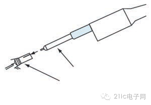
Figure 2. Measuring the output noise . When measuring, we also need to factor in the possible propagation delay of the meter. Most current probes have a propagation delay that is greater than the voltage probe. Therefore, the measurement of the voltage and current waveforms must be displayed at the same time to ensure the accuracy of the measured numbers, unless the different delays are equalized by the human hand.
The current probe also places the inductor into the circuit. A typical current probe will input a 600nH inductor. For high-frequency circuit design, since the inductance that the circuit can withstand cannot exceed 1mH, the inductance input through the probe will affect the accuracy of the di/dt current measurement, and even cause a large error in the measured number. If the inductor is saturated, another more accurate method can be used to measure the amount of current. For example, we can measure the voltage of a small shunt resistor along with the inductor serial. Whether the magnetic design of the magnetic core is reliable is another problem that is often overlooked. Most output inductors use iron powder cores because iron powder is the lowest cost material. About 95% of the iron powder core components are pure iron particles, and these iron powder particles are bonded together using an organic binder. These glues also separate each iron powder particle, so that the inside and outside of the core are filled with a ventilating space.
Iron powder is a raw material that constitutes a core, but iron powder contains a small amount of impurities such as manganese and chromium, and these impurities affect the reliability of the core, depending on the amount of impurities contained. We can use a spectroscopic electron microscope (SEM) to carefully look at the cross section of the core to determine the relative distribution of impurities. Whether the core is reliable or not depends on whether the material is predictable and whether its supply is stable and reliable.
If the iron powder core is in a high temperature environment for a long time, the core loss may increase, and once the loss is increased, it will never recover, because the organic binder will decompose and the eddy current loss will increase. This phenomenon can be called thermal aging, and may eventually lead to thermal runaway of the core.
The core loss is affected by many different factors such as AC flux density, operating frequency, core size and material type. In the case of high frequency operation, most of the losses are eddy current losses. If operated at low frequencies, the hysteresis loss is the largest loss.
Eddy current losses cause the core to be heated, so that efficiency is also affected and falls. The reason for the eddy current loss is that the object caused by the ferromagnetic substance is affected by different magnetic fluxes at different times to cause a circulating current in the object. We can reduce the eddy current loss by using a piece of ferromagnetic sheet instead of solid ferromagnetic material as the core material. For example, a Metglas wound in a tape is such a core. Other ferromagnetic product suppliers such as Magnetics also produce magnetic cores wound with tape.
Magnetic core product suppliers such as Micrometals provide engineers and engineers who design magnetic products with the latest information and calculations on core aging. Iron powder cores using inorganic binders do not appear to be subject to heat aging. Such cores are already on the market and Micrometals' 200C series cores are among these products. Breakdown of synchronous buck converter
Synchronous buck converters are widely used in power systems such as point-of-load power supply systems (POL) or point-of-use power supply systems (PUPS) (Figure 3). This synchronous buck converter uses high-side and low-side MOSFETs to replace the clamp diodes of traditional buck converters to reduce load current losses.

Figure 3, synchronous buck converter
Engineers often overlook the problem of "breakdown" when designing buck converters. Whenever the high-side and low-side MOSFETs are fully or partially activated at the same time, a "breakdown" occurs, allowing the input voltage to deliver current directly to ground. The breakdown phenomenon causes the current to spike at the moment of the switch, making the converter unable to perform its highest efficiency.
We cannot use a current probe to measure the breakdown, because the inductance of the probe can seriously interfere with the operation of the circuit. We can check the gate/source voltages of the two field effect transistors (FETs) to see if there are spikes. This is another way to detect the breakdown phenomenon. (The gate/source voltage of the upper MOSFET can be monitored differentially.)
We can use the following methods to reduce the occurrence of breakdown. The use of a controller chip with a "fixed dead time" is one of the possible solutions. This controller chip ensures that a delay occurs after the upper MOSFET is turned off before the underlying MOSFET is restarted. This method is simpler, but it must be very careful when it is actually implemented. If the dead time is too short, the breakdown may not be prevented. If the dead time is too long, the conductance loss will increase because the diode built into the underlying FET is always on during the entire dead time. Since this diode conducts during the dead time, the efficiency of the system using this method depends on the characteristics of the built-in diode of the underlying MOSFET.
Another way to reduce the breakdown is to use a controller chip with "adaptive dead time". The advantage of this method is that the gate/source voltage of the upper MOSFET can be constantly monitored to determine when the underlying MOSFET is enabled.
When the high-side MOSFET is started, the dv/dt spike appears at the gate of the low-side MOSFET through inductive sensing, which pushes up the gate voltage (Figure 4). If the gate/source voltage is high enough to activate it, a breakdown will occur.

Figure 4. The dv/dt induced level amplitude adaptive dead time controller present in the low-side MOSFET is responsible for monitoring the gate voltage of the MOSFET externally. Therefore, any newly added external gate resistors will divide the voltage of the controller's built-in pull-down resistor so that the gate voltage will actually be higher than the voltage monitored by the controller.
Predictive gate drive is another possible solution by using a digital feedback circuit to detect the conduction of the internal diode and adjusting the dead time delay to minimize the conduction of the built-in diodes, ensuring maximum efficiency. If this method is used, the controller chip needs to add more pins, so that the cost of the chip and the power module will increase. It is important to note that even with a predictive gate drive, there is no guarantee that the FET will not be activated by the inductive sensing of dv/dt.
Delaying the startup of the high-side MOSFET also helps reduce breakdowns. Although this method can reduce or completely eliminate the breakdown phenomenon, the disadvantage is that the switching loss is higher and the efficiency is also reduced. If we choose a better MOSFET, it will also help reduce the dv/dt inductor voltage amplitude that appears at the gate of the underlying MOSFET. The higher the ratio between Cgs and Cgd, the lower the inductor voltage that appears on the MOSFET gate.
The test conditions for breakdown are often overlooked, for example during load transients—especially whenever the load has been removed or suddenly reduced—the controller will continue to generate narrow-frequency pulses. Most current high current systems use a multi-phase design that uses a driver chip to drive the MOSFET. But using a driver chip can make the breakdown problem more complicated, especially when the load is in a transient state. For example, the interference of narrow-frequency drive pulses, coupled with the propagation delay of the driver, can lead to breakdowns.
Most driver chip manufacturers specifically specify that the pulse width of the controller must not be lower than a minimum requirement. If it is lower than this minimum requirement, there will be no gate of the pulse input MOSFET. In addition, the manufacturer adds a dead time (TRT) to the driver chip to enhance the accuracy of adaptive conversion timing. The method is to add a resistor between the set dead time pin and ground to set the dead time to determine the dead time during the high and low end conversion. This dead time setting function plus propagation delay turns off the complementary MOSFETs during the conversion process to avoid breakdown of the synchronous buck converter.
Reliability Any module must pass rigorous testing at an early stage to ensure that the design is complete and reliable so that unexpected problems do not occur in the final stages of the production process. The modules must be tested in the customer's system to ensure that all factors that may cause the system to fail, such as cooling fan failures, intermittent fan pauses, etc., can be fully considered. Engineers with a decentralized structure want the system to be designed for continuous use for many years with little or no failure. Since the test figures show that the MTBF of the power module is up to several million hours, it is not difficult to achieve this goal.
But what is often overlooked is the reliability of printed circuit boards. According to current trends, the area of ​​printed circuit boards is getting smaller and smaller, but the amount of current that needs to be processed is getting larger and larger, so an increase in current density may cause concealed or other vias to fail to perform normal functions.
Printed circuit boards have partially hidden vias that must carry a large amount of current. For these hidden vias, there must be enough copper protection around them to ensure a more reliable and durable design. This type of guard also suppresses the extent of thermal expansion of the z-axis. If this is not the case, the hidden via will be exposed as soon as the ambient temperature of the printed circuit board changes during production and during product use. Engineers must thoroughly review the design of printed circuit boards with reference to the expertise of printed circuit board manufacturers, and printed circuit board manufacturers can provide professional advice on the reliability of printed circuit board design based on their production capabilities.
Summary : If we want to use a power module to build a reliable power supply system, we must solve the problem of design reliability. The above focuses on several major issues, including the reliability of iron powder cores, the characteristics of magnetic systems, the breakdown of synchronous buck converters, and the reliability of printed circuit boards in high current systems.
72W Medical Adapter,72W Medical Power Supply Adapter,72W Medical Ventilator Adapter,72W Medical Outlet Adapter
Shenzhen Longxc Power Supply Co., Ltd , https://www.longxcpower.com