Detailed description of the circuit schematic of the photoelectric encoder
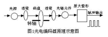
Working principle: When the axis of the photoelectric encoder rotates, both A and B lines produce pulse output. The A and B two-phase pulses are separated by a phase angle of 90 degrees, so that the rotation direction of the photoelectric encoder and the motor speed can be measured. If the A phase pulse is ahead of the B phase pulse, the photoelectric encoder is forward rotation, otherwise it is reversed. The Z line is zero pulse line, and the photoelectric encoder generates one pulse per revolution. It is mainly used for counting. The A line is used to measure the number of pulses, and the B line is matched with the A line to measure the direction of rotation.

N is the motor speed
n=ND measurement-ND theory
For example: the speed of our car is 1.5m / s, the diameter of the wheel is 220mm, C = D * Pi, the motor is controlled at 21.7 rev / sec, according to the specifications of the servo system, the motor speed is 1500 rev / min, so it can be obtained When ND=21.7*60=130 rpm, the number of pulses output per second by the optical code disc is:
PD=130600/60=1300 pulses
When the number of detected pulses deviates from the calculated standard value, the incremental voltage ΔU output to the servo system can be calculated according to the correspondence between the voltage and the number of pulses, and the D/A conversion is performed to calculate the increase. The number of pulses is equal to the number of pulses.
The longer the run time, the longer the route, and the more deviations from our prefabricated route. At this time, the system starts the position loop, continuously measures the number of pulses output by the photoelectric encoder per second, and compares it with the standard value PD (ideal value) to calculate the increment ΔP and convert it into the corresponding D/A. Output digital quantity, reduce the number of pulses of the input motor through the controller, subtract the increment on the basis of the original output voltage, forcing the motor speed to drop, and stop the adjustment when the measured ΔP is approximately zero, so that The motor speed is always controlled within the permissible range.
According to the detection principle, the encoder can be divided into optical, magnetic, inductive and capacitive. According to its scale method and signal output form, it can be divided into three types: incremental, absolute and hybrid.
1.1 incremental encoder
The incremental encoder directly uses the photoelectric conversion principle to output three sets of square wave pulse A, B and Z phases; the A and B sets of pulse phase difference 90 sea servants æ„•å˜ æ„•å˜ æ„•å˜ æ„•å˜ é²‚ 鲂 鲂 为 为 为Pulse for reference point positioning. Its advantage is that the principle structure is simple, the average mechanical life can be more than tens of thousands of hours, the anti-interference ability is strong, the reliability is high, and it is suitable for long-distance transmission. The disadvantage is that the absolute position information of the shaft rotation cannot be output.
1.2 absolute encoder
The absolute encoder is a sensor that directly outputs digital quantity. There are several concentric code channels in the radial direction on its circular code disc. Each track is composed of a transparent and opaque sector, and the adjacent code channel fan The number of zones is doubled. The number of code channels on the code wheel is the number of bits in its binary digit. The light source is on one side of the code wheel and the light sensor on the other side of each code channel. When the code wheel is in different positions When each photosensitive element converts a corresponding level signal according to whether it is illuminated or not, a binary number is formed. The feature of this type of encoder is that it does not require a counter, and a fixed digital code corresponding to the position can be read at any position of the rotary shaft. Obviously, the more code channels, the higher the resolution. For an encoder with N-bit binary resolution, the code wheel must have N code channels. At present, there are 16 absolute encoder products in China.
Absolute encoders use the natural binary or cyclic binary (Gray code) method for photoelectric conversion. The absolute encoder differs from the incremental encoder in that it has a light-transmissive, opaque line pattern on the disc. The absolute encoder can have several codes, and the absolute position is detected based on the code on the read code disc. The coded design can use binary code, cyclic code, two's complement code, and the like. It is characterized by:
1.2.1 The absolute value of the angular coordinates can be read directly;
1.2.2 There is no cumulative error;
1.2.3 The position information will not be lost after the power is removed. However, the resolution is determined by the number of bits in the binary, that is, the accuracy depends on the number of bits, and there are currently 10, 14 and so on.
1.3 hybrid absolute encoder
A hybrid absolute encoder that outputs two sets of information: one set of information for detecting the magnetic pole position with absolute information function and the other set with the output information of the incremental encoder.
The photoelectric encoder is an angle (angular velocity) detecting device, which converts the angular amount input to the shaft into a corresponding electric pulse or digital quantity by using the photoelectric conversion principle, and has the advantages of small volume, high precision, reliable operation, digitization of the interface, and the like. . It is widely used in CNC machine tools, rotary tables, servo drives, robots, radars, military target determination and other devices and equipment that need to detect angles.
Recommended reading:
What is a photoelectric encoder?
Photoelectric encoder wiring diagram
RF Connector Adapter,RF Adapters SMB To SMC,RF Adapters N To BNC,Plug To Plug Adapter Connectgor
Xi'an KNT Scien-tech Co., Ltd , https://www.honorconnector.com