Optimizing the accelerator design of FPGA-based deep convolutional neural network
CNN has been widely used for image recognition because it mimics the behavior of biological optic nerves to achieve high recognition accuracy. Recently, the rapid growth of modern applications based on deep learning algorithms has further improved research and implementation. In particular, a number of deep CNN accelerators based on FPGA platforms have been proposed with high performance, reconfigurability, and fast development cycles.
Although FPGA accelerators have demonstrated better performance than general-purpose processors, the accelerator design space is not well explored. A serious problem is that the computational throughput of an FPGA platform does not match the memory bandwidth very well. As a result, existing solutions either do not take full advantage of logical resources or do not make full use of memory bandwidth to achieve optimal performance. At the same time, the increasing complexity and scalability of deep learning applications has made this problem even worse.
To overcome this problem, we propose a design analysis method using the roofline model. For any CNN design, we quantify its computational throughput and required memory bandwidth using different optimization techniques (cyclic block, transform). With the help of the roofline model, we can find the solution with the best performance and lowest FPGA resource requirements.

As a case study, we implemented a CNN accelerator on the VC707 FPGA board and compared it to the previous solution. Our implementation achieves a peak processing capability of 61.62 GFLOPS at 100 MHz operating frequency, which is much better than the previous solution.
ã€1 Introduction】CNN is a well-known deep learning architecture, which has been extended from artificial neural networks. It has been widely used in different applications, including video surveillance, mobile robot vision, data center image search engine, etc. [6][7][8][10 】ã€14】
Inspired by biological optic nerve behavior, CNN uses multiple layers of neurons to process data, resulting in high accuracy in image recognition. Recently, the rapid growth of modern applications based on deep learning algorithms has further improved DCNN research.
Due to CNN's special computing model, it is not efficient for a general-purpose processor to implement CNN, so it is difficult to meet performance requirements. Therefore, recently different accelerators based on FPGA, GPU and even ASIC have been proposed [3] [4] [9] to improve CNN design performance. Among these solutions, FPGA-based accelerators attract more and more researchers' attention because of their better performance, energy efficiency, rapid development cycle and reconfigurability [1] [2] [3] [6] [ 12] [14].
There are many potential solutions for any CNN algorithm implementation, resulting in a huge design space. In our experiments, we found that the performance of different scenarios using the same FPGA logic resources was a maximum of 90%. Finding the optimal solution is not worthwhile, especially when considering the computing resources and memory bandwidth limitations of the FPGA platform. In fact, if an accelerator structure is not carefully designed, its computational throughput does not match the memory bandwidth. Underutilization of logical resources or memory bandwidth means performance degradation.
Unfortunately, FPGA technology advancements and deep learning algorithms have complicated the problem at the same time. On the one hand, the increasing logic resources and memory bandwidth of the current FPGA platform expand the design space, and different FPGA optimization techniques (such as loop partitioning and transformation) will further expand the design space. On the other hand, in order to meet the needs of modern applications, deep learning scalability and complexity continue to grow. Therefore, it is more difficult to find the optimal solution in a huge design space, and there is a need for a method for efficiently searching the FPGA-based CNN design space.
In order to efficiently search the design space, this paper proposes a method of analysis and design. Our work is better than the previous method for two reasons:
First, [1, 2, 3, 6, 14] focuses on computational engine optimization, either ignoring external memory operations or directly connecting their accelerators to external memory. Our work considers buffer management and bandwidth optimization.
Second, [12] reduces external data acquisition through data reuse to achieve acceleration. But this approach does not have to lead to optimal global performance. In addition, their method needs to be reconfigured for each layer, which is not convenient. Our accelerators can perform different layers of calculations without reprogramming the FPGA.
The main contributions of this paper are as follows:
* Quantitative analysis of possible solution throughput and required memory bandwidth;
* Under computational resource and memory bandwidth constraints, we use the roofline model to identify all possible solutions and discuss how different layers look for optimal solutions;
* We propose a CNN accelerator design that uses a uniform loop expansion factor for each layer;
* Implemented the CNN accelerator and achieved 61.62 GFLOPS processing performance, which is currently optimal;
[2. Background]2.1 CNN Foundation
Inspired by neuroscience research, CNN has become more and more prominent in the field of computer vision and AI ([11][9]) after more than 20 years of evolution. As a classic supervised learning algorithm, CNN uses feedforward processing for recognition and feedback for training. In industrial practice, many application designers train CNN offline and then implement real-time tasks with trained CNN. Therefore, the feedforward calculation speed is more important. This article focuses on designing feedforward computational acceleration with an FPGA-based accelerator.
A typical CNN consists of two parts: a feature extractor + a classifier.
A feature extractor is used to filter the input image to produce a feature map representing different features of the image. These features may include corners, lines, arcs, etc., which are insensitive to position and deformation. The output of the feature extractor is a low-dimensional vector containing these features.
The vector is fed into the classifier (usually based on traditional artificial neural networks). The purpose of the classifier is to determine the likelihood that the input belongs to a certain category.
A typical CNN includes multiple compute layers. For example, the feature extractor may include several convolutional layers and an optional downsampling layer. Figure 1 shows the calculation of the convolutional layer.
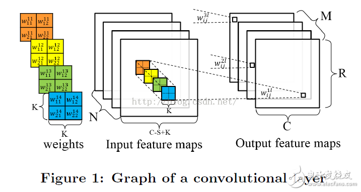
The convolutional layer receives N feature maps as inputs, and each input feature map is convolved by a K*K kernel to produce one pixel of the output feature map. The spacing of the sliding windows is S, which is generally less than K. A total of M output feature maps are generated for the next convolutional layer. The pseudo code for the convolutional layer is as follows:
For(row = 0; row < R; row ++)
{
For(col = 0; col < C; col ++)
{
For(to = 0; to < M; to ++)
{
For(TI = 0; TI < N; TI ++)
{
For(i = 0; i < K; i++)
{
For(j = 0; j < K; j++)
{
Output_fm[to][row][col] += weights[to][TI][i][j] * input_fm[ti][S * row + i][S * col + j];
}
}
}
}
}
}
In the feedforward calculation perspective, the previous paper [5] proved that the volume and operation will occupy more than 90% of the total calculation time, so we focus on accelerating the convolution layer. Later, we will consider integrating other optional layers, such as the sampling layer and the largest pooling layer.
a real CNN
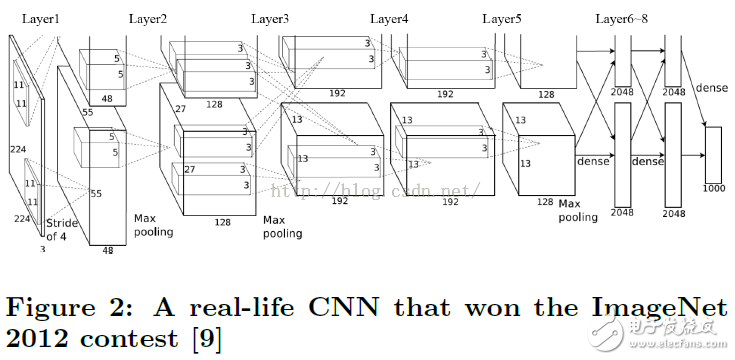
Figure 2 shows a real CNN application, taken from [9]. The CNN consists of 8 layers, the first 5 layers are convolutional layers, and the 6th to 8th layers are fully connected artificial neural networks. The algorithm receives a 3-channel 224x224 input image (converted from the original 256x256 three-channel RGB image) and outputs a 1000-dimensional vector representing the likelihood of 1000 categories.
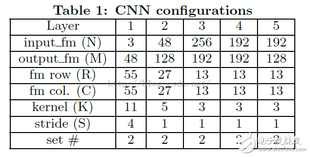
The first layer input is three 224x224 resolution feature maps, outputting 96 55x55 resolution feature maps, and the output is divided into two sets, each of which has 48 sets of feature maps. Table 1 records the configuration of the CNN.
2.2 Roofline model
Computing and communication are two fundamental limitations of system throughput optimization. An implementation may be computationally constrained or limited in access. [15] Developed a roofline performance model to correlate system performance with off-chip storage bandwidth and peak computing performance.
Equation (1) represents the reachability of a specific hardware platform, using GFLOPS as an evaluation indicator.
The actual GFLOPS of an application will not be higher than the minimum of these two: the first is the peak computing power (calculated upper limit) provided by all available computing resources, and the second is the system memory bandwidth available for a given calculation-communication ratio. Maximum floating point performance supported (IO bandwidth cap). The computation-to-communication ratio, also known as the amount of computation per DRAM transfer, represents the amount of DRAM access required for a particular system implementation.
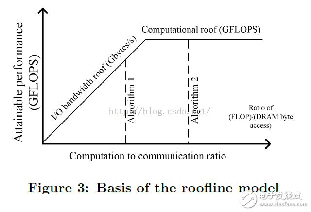
Figure 3 visualizes the roofline model, showing the upper limit of the calculation and the upper limit of the IO bandwidth. Algorithm 2 has a higher computation-communication ratio, or better data reuse, than Algorithm 1. It is seen from the figure that Algorithm 2 takes full advantage of all hardware computing resources and performs better than Algorithm 1.
[3. Accelerator Design Exploration]
This section first provides an overview of our accelerator architecture and presents several design challenges on the FPGA platform. In order to overcome these challenges, we have proposed corresponding optimization techniques.
3.1 Design overview
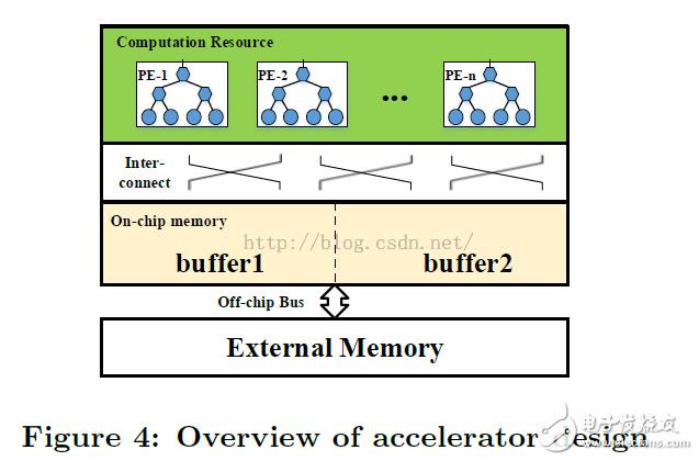
As shown in Figure 4, a CNN accelerator design includes: processing unit (PE), on-chip cache, external memory, and on-chip and off-chip interconnects. PE is the basic unit of computation for convolution. All data for processing is placed in external memory. Due to the on-chip resource limitation, the data is first buffered to the on-chip buffer and then sent to the PE. Here double buffering is used to mask the transmission time to the calculation time. On-chip interconnects are used for PE and on-chip buffered communications.
There are several design challenges on the FPGA platform that hinder the efficient CNN accelerator design: First, there is only a small fraction of the on-chip data, so loop tiling is necessary, and inappropriate loop partitioning may reduce data reuse and Data parallel processing efficiency.
Second, PE and buffer organization and their interconnection should be carefully considered so that on-chip data can be processed efficiently. Third, the data processing throughput of the PE should match the off-chip memory bandwidth of the FPGA platform.
In this section we start with Code1 and provide continuous steps for optimal processing efficiency.
The code that uses loop blocking is as follows:
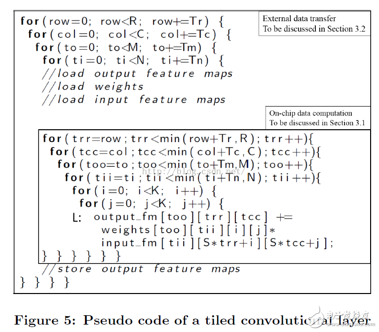
Note that the loop variables i and j are not chunked because the convolutional layer kernel size K in the CNN is too small (3~11).
Second, we discussed computational engine optimization and linked computational performance to blocking coefficients.
Third, we use data reuse techniques to reduce external access, and establish a connection between the computation-access ratio and the blocking factor;
Fourth, using the above two variables, we define the design space and find the optimal solution on the FPGA platform;
Fifth, we discussed how to choose the best accelerator for multi-layer CNN applications.
General Purpose Steel Wire Rope
Aircraft Cable And GP Steel Wire Rope
Widely used in the industry of Port Machinery, Vessels, Elevators, Engineering Machinery, Mining, Petroleum, etc
GAC: 7x7 7x19
GP steel wire rope: 1x7 1x19 6x7 7x7 6x19 7x19 6x12 6x24 6x37
Surface: (1) hot-dip galvanized; (2) electric galvanized; (3) black; (4) PVC coating; (5) stainless steel; (6) zinc + aluminum, etc.
Steel Wire Rope,Galvanized Wire Rope,Galvanized Steel Wire Rope,Galvanized Aircraft Cable
ROYAL RANGE INTERNATIONAL TRADING CO., LTD , https://www.royalrangelgs.com