Three LED lights cycle flashing circuit diagram
Three LED lights cycle flashing circuit 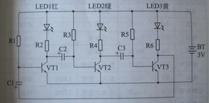
This is the principle of the circuit schematic circuit:
VT2
Due to the difference in actual parameters of electronic components, it is impossible to conduct at the same time. It is assumed that the VT1 transistor is turned on first, the red lamp is lit (R2 is the current limiting resistor), C2 is the capacitor, and the capacitor voltage cannot be abruptly changed, resulting in the VT2 base voltage. When the time is 0, (VT1 is connected to the current capacitor is equivalent to short circuit to ground), VT2 base voltage is 0, VT2 is cut off, green light is not bright, due to VT2 cutoff, VT3 base voltage rises, VT3 turns on, yellow light shines, Now only the red and yellow lights are on. As time goes by, capacitor C2 is charged through R3. When the voltage rises above 0.7V, VT2 turns on.
The green light is on, the VT3 base voltage is pulled low due to VT2 conduction, VT3 is cut off, the yellow light is extinguished, then the capacitor C3 is charged through the resistor R5, the voltage is raised to 0.7V, VT3 is turned on, the yellow light is on, and VT1 is turned on due to VT3. And cut off. . . . . . This circuit follows this cycle and the lights illuminate one by one. 

Suizhou simi intelligent technology development co., LTD , https://www.msmvape.com