Depth description of four types of sensors based on magnetic sensors
One of the four great inventions of our great Chinese ancestors, the compass, is no one knows. For modern sensor technology, it can be regarded as the originator of magnetic sensors.
In today's electronic age, magnetic sensors are widely used in motors, power electronics, automotive, industrial automation, robotics, office automation, household appliances, and various safety systems.
Magnetic sensor
A magnetic sensor is a device that converts a magnetic property change of a sensitive component caused by external factors such as a magnetic field, a current, a stress strain, a temperature, and light into an electrical signal to detect a corresponding physical quantity in this manner. Used to sense speed, motion and direction, applications include automotive, wireless and consumer electronics, military, energy, medical and data processing.
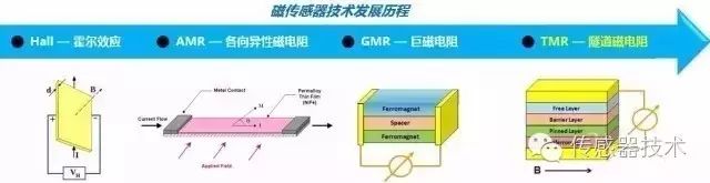
According to the development of technology, the magnetic sensor market is mainly divided into four categories: Hall effect sensor, anisotropic magnetoresistive (AMR) sensor, giant magnetoresistance (GMR) sensor tunnel magnetoresistance (TMR) sensor. Hall effect sensors have the longest history and are widely used. With continuous technology development, various magnetic sensors have been born with superior performance and higher reliability. Hall Effect Sensor In 1879, the American physicist Hall discovered the Hall effect when studying metal conduction mechanisms. However, due to the weak Hall effect of metal, there has been no practical application. Until the Hall effect of the semiconductor is found to be much stronger than that of the metal, the Hall element is fabricated using this phenomenon. A control current I is applied across the semiconductor film, and a uniform magnetic field having a magnetic induction intensity of B is applied in the vertical direction of the film. The electrons and holes in the semiconductor are subjected to Lorentz forces in different directions and are concentrated in different directions. An electric field is generated between the collected electrons and holes. After the electric field strength is balanced with the Lorentz force, it does not accumulate. This phenomenon is called the Hall effect. The built-in potential difference that is generated in the direction perpendicular to the current and the magnetic field is called the Hall voltage U. The relationship between the Hall voltage U and the thickness d of the semiconductor film, the electric field B and the current I is U = k (IB / d). Here k is the Hall coefficient, which is related to the semiconductor magnetic material.
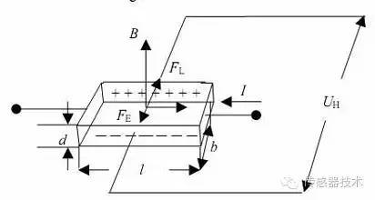
Hall effect diagram
Hall sensors are fabricated using the Hall effect principle, mainly including Hall linear sensors, Hall switches, and magnetometers. 1. The linear Hall sensor consists of a Hall element, a linear amplifier, and an emitter follower that outputs an analog quantity. The output voltage is linear with the applied magnetic field strength. As shown in the figure below, there is a good linearity in the magnetic induction range of B1 to B2. When the magnetic induction exceeds this range, it is saturated.
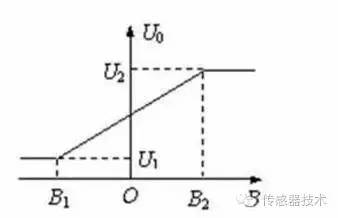
Linear Hall sensor working principle
Hall linear devices have a wide magnetic field measurement range and can recognize magnetic poles. Its application fields include electric locomotives, underground railways, trolley buses, railways, etc. It can also be used in frequency converters for monitoring power, photovoltaic DC cabinets to monitor the real-time output current of photovoltaic combiner boxes, and motor protection. Linear Hall sensors can also be used to measure position and displacement, and Hall sensors can be used for level detection, water flow detection, and more. 2. The switching Hall sensor consists of a voltage regulator, a Hall element, a differential amplifier, a Schmitt trigger and an output stage that outputs a digital quantity.
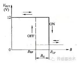
Switching Hall sensor working principle
Hall switch devices are non-contact, wear-free, clear output waveform, no jitter, no rebound, high position repeatability, wide operating temperature range, up to -55 ° C ~ 150 ° C. The switch-type Hall sensor completes a switching action after a change in the strength of the magnetic field, and outputs a digital signal, which can calculate the speed of the car or machine, the speed sensor in the ABS system, the car speedometer and the odometer, and the automatic door switch of the locomotive. , brushless DC motor, car ignition system, access control and burglar alarm, vending machine, printer, etc. 3. Magnetometer
The potential difference generated by the Hall effect is used to measure the magnitude and polarity of the external magnetic field. The magnetometer is a planar device using a CMOS process. The process is simpler than the general IC. Generally, a sensor device is formed on the N-well on the P-type substrate, and the sensor is connected to other circuits (such as an amplifier, an adjustment processor, etc.) through the metal electrode.
However, the Hall sensor thus designed can only sense the change of the magnetic field perpendicular to the surface of the die, thus increasing the magnetic flux concentrator. In principle, it is to add a layer of permalloy to the original die. , can detect the magnetic field parallel to the direction of the die. Thus, the Hall sensor achieves a leap-forward development from a single-axis to a three-axis magnetometer.
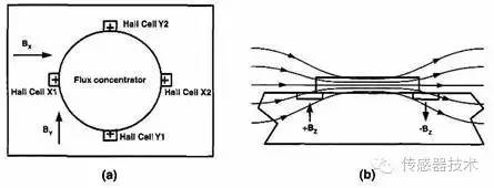
Figure (a) Adds a top view of the Hall sensor of the flux concentrator
Figure (b) Adding a cross-sectional view of the Hall sensor of the flux concentrator The magnetometer is widely used in mobile terminals such as smartphones, tablets and navigation devices, and has a huge market prospect. At the same time, the magnetometer can be combined with an accelerometer to form a 6-axis electronic compass. The combination of three inertial sensors (plus a gyroscope) can also realize a 9-axis combined sensor, which constitutes a more powerful inertial navigation product. Anisotropic Magnetoresistive (AMR) Sensors When a metal or semiconductor encounters an applied magnetic field, its resistance value changes with the magnitude of the applied magnetic field. This phenomenon is called the magnetoresistance effect, and the magnetoresistive sensor uses the magnetoresistance effect. to make.
In 1857, Thomson discovered the anisotropic magnetoresistance effect of permalloy. For ferromagnetic metals with anisotropic properties, the change in magnetoresistance is related to the angle between the magnetic field and the current. Common metals of our kind are iron, cobalt, nickel and their alloys.
When the external magnetic field is at a zero angle to the direction of the built-in magnetic field of the magnet, the resistance does not change with the change of the applied magnetic field; however, when the external magnetic field has a certain angle with the built-in magnetic field of the magnet, the internal magnetization vector of the magnet may be biased. The film resistance decreases, and we call this property an anisotropic magnetoresistive sensor (AMR). The effect of the magnetic field is shown below.
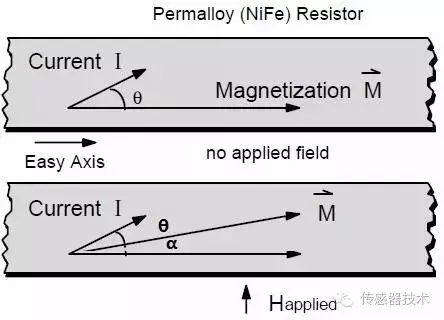
AMR effect of permalloy

Relationship between magnetoresistance change value and angle change
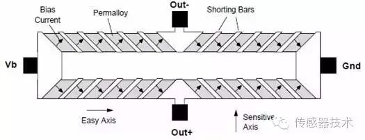
The resistance R of the film alloy changes due to the change in angle, and the resistance and magnetic field characteristics are nonlinear, and each resistance does not correspond to the unique applied magnetic field value. From the above figure, we can see that when the current direction is parallel to the magnetization direction, the sensor is most sensitive. When the current direction and the magnetization direction are at an angle of 45 degrees, the general reluctance works near the linear region in the figure, so that the output can be realized. Linear characteristics. The basic structure of the AMR magnetic sensor consists of four magnetic reluctances that make up the Wheatstone bridge. The power supply is Vb, and the current flows through the resistor. When a bias magnetic field H is applied to the bridge, the magnetization directions of the two oppositely placed resistors will rotate toward the current direction, and the resistance of the two resistors will increase; and the magnetization of the other two oppositely placed resistors The direction will rotate in the opposite direction of the current, and the resistance of the two resistors will decrease. The external magnetic field value can be obtained by testing the two output terminals of the bridge to output a differential voltage signal.
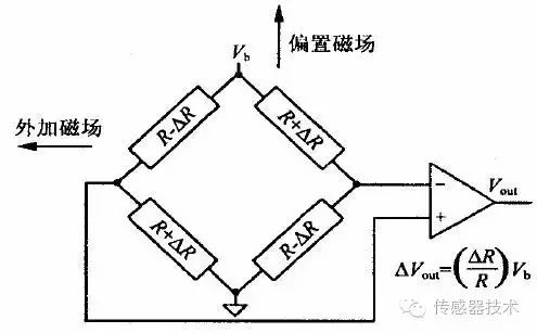
AMR magnetoresistive sensor equivalent circuit
The advantages of anisotropic magnetoresistance (AMR) technology are as follows: 1. The most excellent magnetic field range of anisotropic magnetoresistance (AMR) technology is centered on the earth's magnetic field, and the sensor with the earth's magnetic field as the basic operating space. In terms of application, it has a large operating space, and does not need to increase the auxiliary means such as magnetism like the Hall element. 2. Anisotropic magnetoresistance (AMR) technology is the only semiconductor process technology that has been proven to achieve a directional accuracy of one degree in the Earth's magnetic field. Other technologies that achieve the same accuracy are processes that cannot be integrated with semiconductors. Therefore, AMR can be integrated on the same silicon chip as CMOS or MEMS and provide sufficient accuracy. 3. AMR technology requires only one layer of magnetic film, which is simple in process, low in cost, does not require expensive manufacturing equipment, and has cost advantages. 4. AMR technology has high frequency, low noise and high signal to noise ratio characteristics, and there are no limitations in various applications. The AMR magnetoresistive sensor can well sense weak magnetic field measurements in the geomagnetic field, and make various displacement, angle, and rotational speed sensors, various proximity switches, and isolating switches for detecting some ferromagnetic objects such as airplanes and trains. car. Other applications include compasses in various navigation systems, disk drives in computers, various magnetic card machines, rotational position sensing, current sensing, drilling orientation, line position measurement, yaw rate sensors, and head trajectories in virtual reality track. Giant Magnetoresistance (GMR) Sensor Compared to Hall sensors and anisotropic magnetoresistive (AMR) sensors, Giant Magneto Resistance (GMR) sensors are much younger! This is because the discovery of the GMR effect is more than 100 years later than the Hall effect and the AMR effect. In 1988, the German scientist Greenberger discovered a special phenomenon: very weak magnetic changes can lead to very significant resistance changes in magnetic materials. At the same time, the French scientist Fair found in the multi-layer film resistance between iron and chromium that a weak magnetic field change can lead to a sharp change in the magnitude of the resistance, which is more than ten times higher than usual. Fair and Greenberger also won the 2007 Nobel Prize in Physics for their discovery of giant magnetoresistance. The general magnet metal has a resistivity change of 1% to 3% under the applied magnetic field and no magnetic field, but the multilayer film composed of ferromagnetic metal/nonmagnetic metal/ferromagnetic metal can reach 25% at room temperature. It is more obvious at low temperatures, which is also the reason for the giant magnetoresistance effect.
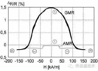
Schematic diagram of resistivity changes of GMR and AMR under an applied magnetic field
"giant" is used to describe such magnetoresistance effects, not only from apparent properties, but also because of their different formation mechanisms. The conventional magnetoresistance is derived from the direct action of the magnetic field on the motion of the electron, and is anisotropic magnetoresistance, that is, the resistance is related to the relative orientation of the magnetization and current. In contrast, the GMR magnetoresistance is isotropic and is essentially independent of the relative orientation of magnetization and current.
The giant magnetoresistance effect depends only on the relative orientation of the magnetic moments of adjacent magnetic layers. The operation of the external magnetic field is only to change the relative orientation of the magnetic moments of adjacent ferromagnetic layers. In addition, the more important significance of the GMR effect is to lay the foundation for further exploration of new physics, such as Tunneling Magnetoresistance (TMR), Spintronics, and new sensor technologies.
The first commercial application of the GMR effect was in 1997, a hard disk data reading probe marketed by IBM. So far, giant magnetoresistance technology has become the standard technology for almost all computers, digital cameras, and MP3 players around the world. The material structure of the GMR sensor has a GMR effect, and the material mainly includes a multilayer film, a particle film, a nanoparticle alloy film, a magnetic tunneling oxide, and a giant magnetoresistance film. Among them, the structure of the spin valve type multilayer film is widely used in the current GMR magnetoresistive sensor. The spin valve mainly has a free layer (magnetic material FM), an isolation layer (non-magnetic material NM), a pinning layer (magnetic material FM) and an antiferromagnetic layer (AF) four-layer structure.
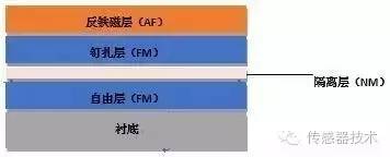
Basic structure of spin valve GMR magnetoresistive sensor
The GMR magnetoresistive sensor consists of four giant magnetoresistances to form a Wheatstone bridge structure, which reduces the influence of the external environment on the stability of the sensor output and increases the sensitivity of the sensor. When the magnetic moments of adjacent magnetic layers are distributed in parallel, the two FM/NM interfaces exhibit different resistance states, one interface is in a high-resistance state, and one interface is in a low-resistance state. The spin conduction electrons can move freely within the crystal, as a whole. The device exhibits a low-resistance state; when the magnetic moments of adjacent magnetic layers are anti-parallel, the conduction electrons of the two spin states encounter another magnetic moment after passing through a magnetic layer whose magnetic moment orientation is the same as its spin direction. The magnetic layer is oriented opposite to its spin direction, and is strongly scattered there. No spin state electrons can pass through the FM/NM interface, and the device exhibits a high resistance state.
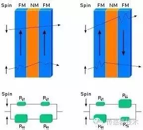
Equivalent circuit diagram under the action of parallel magnetic field and anti-parallel magnetic field
GMR magnetoresistive sensors are commercialized later than Hall sensors and AMR magnetoresistive sensors. The manufacturing process is relatively complex and the production cost is high. However, it has the advantages of high sensitivity, ability to detect weak magnetic field and good signal, and small influence of temperature on device performance, so the market share is stable. GMR magnetoresistive sensors are involved in consumer electronics, industrial, defense, military, and medical biology. Tunnel magnetoresistance (TMR) sensor
As early as 1975, Julliere observed the TMR (Tunnel Magneto-Resistance) effect in Co/Ge/Fe magnetic tunnel junctions (MTJs). However, this discovery did not attract people's attention at the time. In the next decade or so, research on the TMR effect has progressed very slowly. Under the in-depth study of the GMR effect, the TMR effect of the same magnetoelectronics began to receive attention. In 2000, the discovery of MgO as a tunnel insulation layer was an opportunity for the development of TMR magnetoresistive sensors.
In 2001, Butler and Mathon each made a theoretical prediction: with iron as ferromagnet and MgO as insulator, the tunnel magnetoresistance can vary by several thousand. In the same year, Bowen et al. first demonstrated the TMR effect of magnetic tunnel junctions (Fe/MgO/FeCo). In 2008, the S. Ikeda and H. Ohno team at Tohoku University in Japan found that the change in resistivity of the magnetic tunnel junction CoFeB/MgO/CoFeB reached 604% at room temperature and exceeded 1100% at 4.2K. The TMR effect has such a large change in resistivity, so the industry is paying more and more attention to the research of TMR effect and commercial product development.
The new magnetoresistance effect sensor that TMR components have only begun to use in industrial applications in recent years, which uses the tunnel magnetoresistance effect of magnetic multilayer film materials to sense the magnetic field, has greater resistance than the previously discovered and practically used AMR components and GMR components. Rate of change. We usually also use the Magnetic Tunnel Junction (MTJ) to refer to the TMR component. The MTJ component has better temperature stability, higher sensitivity, lower power consumption, better linearity, compared to Huo. The element does not require an additional geomagnetic ring structure and does not require an additional set/reset coil structure relative to the AMR element. Material structure and principle of TMR magnetoresistive sensor
From the point of view of classical physics, the sandwich structure of ferromagnetic layer (F1) + insulating layer (I) + ferromagnetic layer (F2) can not achieve the penetration of electrons in the magnetic layer, but quantum mechanics can perfectly explain this. phenomenon. When the magnetization directions of the two ferromagnetic layers are parallel to each other, the electrons of most spin subbands will enter the empty state of most spin subbands in the other magnetic layer, and the electrons of a few spin subbands will also enter the other magnetic layer. In the empty state of a few spin subbands, the total tunneling current is large, and the device is in a low resistance state;
When the magnetization directions of the two layers of magnet layers are anti-parallel, the opposite is true, that is, the electrons of most spin sub-bands will enter the empty state of a few spin sub-bands in another magnetic layer, and the electrons of a few spin sub-bands Entering the empty state of most spin subbands in another magnetic layer, the tunneling current is small and the device is in a high resistance state.
It can be seen that the tunneling current and the tunneling resistance depend on the relative orientation of the magnetization of the two ferromagnetic layers. When the magnetization direction changes, the tunneling resistance changes, so it is called the tunnel magnetoresistance effect.
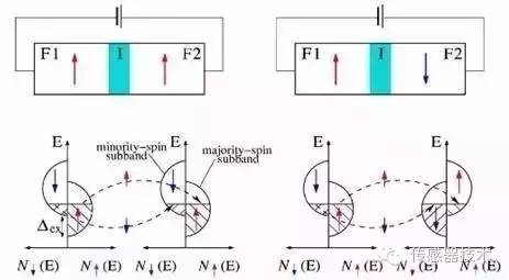
Dual current model for TMR magnetization parallel and anti-parallel
The new magnetoresistance effect sensor that TMR components have only begun to use in industrial applications in recent years, which uses the tunnel magnetoresistance effect of magnetic multilayer film materials to sense the magnetic field, has greater resistance than the previously discovered and practically used AMR components and GMR components. Rate of change. We usually also use the Magnetic Tunnel Junction (MTJ) to refer to the TMR component. The MTJ component has better temperature stability, higher sensitivity, lower power consumption, better linearity, compared to Huo. The element does not require an additional geomagnetic ring structure and does not require an additional set/reset coil structure relative to the AMR element. The following table compares the technical parameters of Hall element, AMR element, GMR component and TMR component, which can clearly and intuitively see the advantages and disadvantages of various technologies.
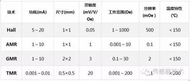
Comparison of technical parameters of Hall element, AMR element, GMR element and TMR element
As a next-generation technology for GMR components, TMR (MTJ) components have completely replaced GMR components and are widely used in the field of hard disk heads. It is believed that TMR magnetic sensing technology will have great development and contribution in the fields of industrial, biosensing, and magnetic random access memory (MRAM). The development of magnetic sensors culminated in the 70s and 80s of this century. The 1990s were the maturity and perfection of these magnetic sensors that have been developed.
Magnetic sensors are widely used and have played an important role in the national economy, national defense construction, science and technology, medical and health fields, and become a major branch of the modern sensor industry. They play an increasingly important role in traditional industrial applications and transformation, resource exploration and comprehensive utilization, environmental protection, bioengineering, and intelligent transportation control.
Ftth Drop Cable Assembly,Ftth Drop Cable Assembly Assembly,Ftth Drop Cable Assembly Adapter,Ftth Drop Cable Assembly Access
Huizhou Fibercan Industrial Co.Ltd , https://www.fibercannetworks.com