Design of high-power electric vehicle charger
Pure electric vehicles use lithium batteries as the power source, and when fully charged, they use electricity to do work to promote the cars. Unlike gasoline-powered cars, which require the addition of gasoline, pure electric vehicles are charged by an external power supply after the power is consumed. Usually, the single mileage is 100 to 200 kilometers. Compared with traditional cars, pure electric vehicles have an unparalleled advantage in terms of cost. They consume about 15 kWh per 100 kilometers and cost 8 yuan, which is only 1/10 of the cost of gasoline-powered cars. At present, the country has embarked on demonstration and promotion of electric vehicles and new energy vehicles, and electric vehicle charging stations are one of the main links. It must achieve common and coordinated development with other fields of electric vehicles.
Charging mode Electric vehicle energy supply system is mainly composed of power supply system, charging system and power storage battery. In addition, it also includes charging monitoring, battery management and smoke alarm monitoring. The charger is an important part of the charging system. Charging stations generally charge cars in three ways: normal charging, fast charging, and battery replacement. Ordinary charging is mostly AC charging. For AC chargers with a capacity not exceeding 5kW, the input is single-phase AC with a rated voltage of 220V and 50Hz, and for AC chargers with a capacity greater than 5kW, the input is three-phase AC with a rated line voltage of 380V and 50Hz . Plug the AC plug directly into the charging port of the electric car, and the charging time will take about 4 to 8 hours. The fast charging is mostly DC charging. The input of the DC charger is three-phase AC with a rated line voltage of 380V and 50Hz. The output voltage generally does not exceed 700V, and the output current generally does not exceed 700A. The output voltage of the AC input isolated AC / DC charger is 50% to 100% of the rated voltage, and when the output current is the rated current, the power factor should be greater than 0.85, and the efficiency should not be less than 90%.
The charger should be able to ensure that the battery voltage, temperature and current of the power battery do not exceed the allowable value during the charging process. The charger should have the functions of anti-output short circuit and anti-reverse connection. The charger can charge at least one of the following three types of power batteries: lithium-ion batteries, lead-acid batteries, and nickel-metal hydride batteries.
The power battery charging mode adopts the "constant current-constant voltage" two-stage charging mode. At the beginning of charging, generally use the optimal charging rate (Lithium ion battery is 0.3C) for constant current charging. (C is the capacity of the battery, such as C = 800mAh, 1C charging rate is the charging current is 800mA) At this stage, due to the low electromotive force of the battery, even if the battery charging voltage is not high, the battery charging current will be very large Limit the charging current. Therefore, the charging at this stage is called "constant current" charging, and the charging current is kept at the current limit value. As the charging continues, the battery's electromotive force continues to rise, and the charging voltage continues to rise. When the battery voltage rises to the highest allowable charging voltage, maintain a constant voltage charge. At this stage, because the battery's electromotive force is still rising, and the charging voltage remains unchanged, the battery's charging current continues to decline in a hyperbolic trend, all the way down to zero. But in the actual charging process, when the charging current is reduced to 0.015C, it means that the charging can be stopped when the charging is full. The charging at this stage is called "constant voltage" charging, and the charging voltage at this stage: U = E + IR is the constant voltage value. This is the basic requirement of the lithium ion power battery pack for the charging mode. In addition, the charging system must also have automatic adjustment of charging parameters, automatic control and automatic protection functions. Especially in the constant voltage charging stage, if the charging voltage of the single battery exceeds the allowable charging voltage, the charger should be able to automatically reduce the charging voltage and current so that the charging voltage of the battery does not exceed the allowable charging voltage to prevent the battery from overcharging Pressure charging. The charging process and changes in charging voltage and current are shown in Figure 1.

Figure 1 Charging curve (n is the number of single cells connected in series in the battery pack)
According to the charging characteristics of the battery and the charging requirements of the electric vehicle power battery pack, the commonly used charging equipment is a charger, which can be divided into two types: DC charger and pulse charger. The DC charger is to isolate and stabilize the DC power supply after the power supply of the power grid is rectified and filtered, and supply the power battery pack for charging. At present, the most used DC charger is a high-frequency switching power supply charger. It has the advantages of small size, light weight, reliable operation, high efficiency, high power factor, strong adaptability to the power grid, small and large power, easy to achieve intelligence and so on. The pulse charger can reduce the polarization phenomenon that occurs when the battery is charged, thereby improving the charging efficiency of the battery, reducing the charging time, and achieving fast charging, but the pulse charger technology needs further research.
The charging time of electric vehicles is long, and the difficulty of charging is a problem for the popularization and application of electric vehicles. Take a large lithium-powered electric bus as an example, with a battery capacity of 700 Ah. The maximum charging current is 210A (equivalent to 0.3C charging rate of 700AH battery capacity), and the maximum charging voltage is 700V (equivalent to 165 lithium battery cell series voltages with a maximum charging voltage of about 4.2V), then the maximum output power of the charger is required to be 245kW. According to the optimal charging requirements, the charging time for charging electric vehicles needs at least 3 hours. Therefore, the charging method of electric vehicles cannot be charged like fuel vehicles at a gas station. If the battery is fully charged in 20 minutes, it must be charged at a charge rate of at least 3C, which is possible for lithium iron phosphate lithium ion batteries.
In summary, the charging method of electric vehicles is still the common charging method, supplemented by rapid supplementary charging. For electric buses, the charging station is located in the bus terminal. Use the valley to charge after work in the evening, the time is 5 to 6 hours. For vehicles running all day, when the driving range is not enough, you can use the intermediate rest time to recharge. The number and capacity of chargers depend on the size of the fleet, and the charging station is managed by the fleet. For example, 12 large lithium-powered electric buses require 12 chargers. For fast charging, 6 chargers can be used for parallel charging, the maximum output power is 1470kW, and the maximum charging current is 2100A (equivalent to the 3C charging rate of 700AH battery). Or 8 chargers are usually used to charge 8 electric vehicles, each of which outputs a maximum charging voltage of 700V and a maximum charging current of 500A (equivalent to a charging rate of 700AH battery consumption of 0.7C). The fast charging mode of 1C ~ 3C has been discussed and applied, but it should be carried out under the premise of battery safety and service life. According to the maximum power configuration of the above charger, the effective total power of the power transformer is about 3000kW or more.
At present, major automobile manufacturers have developed high-production hybrid vehicles and pure electric vehicles. Take BYD E6 pure electric vehicle as an example, the battery type is lithium iron cobalt phosphate battery, the configuration battery capacity is 200Ah, the charging current of 3C is 600A, the nominal voltage is 316.8V (equivalent to 96 lithium iron cobalt phosphate with a charging voltage of about 3.3V Battery cell series voltage). The output power of the charger is 192kW. The fast charging time is 15 minutes and full 80%. The energy consumption per 100 kilometers is about 21.5 kWh, which is equivalent to 1/3 to 1/4 of the consumer price of fuel vehicles.
System structure The input of the high-power electric vehicle charger is three-phase alternating current with a rated line voltage of 380V and 50Hz, with a rated voltage of 700V and a rated current of 600A. The system uses a 19 "standard rack, compact structure, reasonable layout, beautiful appearance. Dimensions: height × width × depth is 2200mm × 600mm × 600mm. Using 60 modules in parallel, each module 10A / 700V, module size : Height × width × depth is 133mm × 425mm × 270mm, 15 layers and 4 columns, divided into four cabinets, the four cabinets can be transported separately, arranged compactly left and right when in use. The front and rear doors of the rack are double open doors, convenient Overhaul. The input positions of the power supply line and the busbar are input at the bottom. The power input circuit breaker and the touch screen of the monitoring unit are installed in the front of the central control cabinet of the host. The schematic diagram of the control structure of the charger is shown in Figure 2.
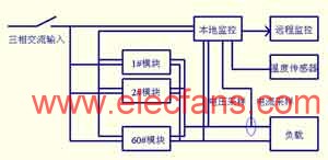
Figure 2 Schematic diagram of the control structure of the charger
The main circuit design of the main circuit of the switching power supply. The block diagram of the high-power high-frequency switching power supply used in the electric vehicle charger is shown in FIG. After 800V, the high-frequency DC / DC half-bridge power converter filters the output DC 700V to charge the power battery. After analysis and calculation, the transformer uses dual E65 cores and 12 turns of the primary coil. According to the highest output voltage of 700V, the lowest input voltage of 780V, and the maximum duty ratio of 0.95, the number of secondary winding turns N2 can be obtained, N2 = (12/780) × (700 / 0.95) = 11.33, considering the leakage inductance, secondary rectification voltage drop and other factors, N2 is 12 turns.
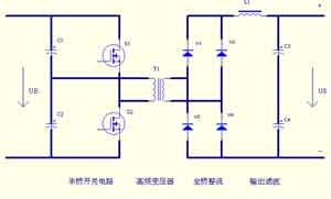
Figure 3 Principle block diagram of the charger power supply
Since the electric vehicle charger is a non-linear load, it will generate harmonics, which is a kind of pollution to the power grid. Effective measures must be taken, such as power factor correction or reactive power compensation, to limit the total harmonics of electric vehicle chargers entering the grid. In order to improve power factor and reduce input grid harmonics, an active power factor correction circuit is used, as shown in Figure 4. It uses a three-phase three-switch three-level BOOST circuit, working in continuous mode, the switch uses a two-way switch composed of two MOSFETs. In the figure, switches S1, S2, and S3 are bidirectional switches. Due to the symmetry of the circuit, the potential at the midpoint of the capacitor VM is approximately the same as the potential at the midpoint of the power grid. Therefore, the current on the corresponding phase can be controlled by the bidirectional switches S1, S2, and S3, respectively. The current amplitude on the corresponding phase increases when the switch is closed, and the diode on the bridge arm turns on when the switch is turned off (when the current is positive, the upper arm diode turns on; when the current is negative, the lower arm diode turns on). Under the effect of the output voltage, the current on the Boost inductor is reduced, thereby realizing the control of the current. The control circuit uses three control chips UC3854A, the phase voltage provides the synchronization signal and the pre-correction signal to the UC3854A through the three-phase isolation transformer, and the current feedback uses the Hall current transformer to control three switches respectively, forming three current feedback inner loops A multi-closed loop system with a voltage feedback outer loop. The advantage of this circuit is its simple structure, requiring only one power switch per phase. With three-level characteristics, the harmonic current is small, and the voltage and current stress of the switch tube are small. No center line is required, no third harmonic, and the power factor is high at full load. The switching stress is small, the turn-off voltage is reduced, the switching loss is low, and the common mode EMI is low.

Figure 4 Three-phase three-switch three-level APFC circuit topology
The DC / DC power converter uses a half-bridge circuit topology, with few power devices, simple control, and high reliability. As shown in Figure 5, the use of MOSFET and IGBT parallel technology makes full use of the advantages of fast MOSFET switching speed and IGBT turn-on voltage reduction. Take measures on the circuit to make the turn-off time of the MOSFET delayed by a certain time than the IGBT, greatly reducing the current tail of the IGBT, reducing the switching on-state losses, improving the efficiency and reliability, and making the output power of the half-bridge circuit Can achieve 7kW. The rectification method adopted on the output side includes half-wave rectification, center-tap full-wave rectification and full-bridge rectification. Due to the high output voltage, the full-bridge rectification has a high utilization rate of the transformer, which is more suitable for this occasion.
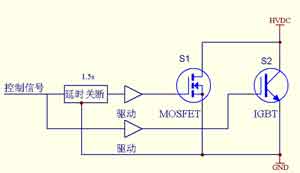
Figure 5 MOSFET / IGBT parallel combination switch circuit
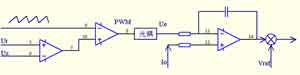
Figure 6 PWM block diagram of forced current sharing method
The system uses the PWM forced current sharing method, and the working block diagram is shown in Figure 6. This is an improved method of combining system voltage control and forced current sharing. Its working principle is to compare the system bus voltage Us with the system reference voltage Ur to generate an error voltage Ue, and use this error voltage to control the PWM modulator. The PWM signal controls the current of each module. The current requirement signal of each module is the same. The PWM signal is compared with the output current of the module through the optocoupler to adjust the reference voltage of the module, thereby changing the output voltage and adjusting the output current to achieve current sharing. In this way, each module is equivalent to a voltage-controlled current source. This current sharing method has high precision, good dynamic response, and many controllable modules, which can easily form a redundant system. Forced current sharing depends on a certain module. If the module fails, the current sharing cannot be achieved, so it is necessary to design the module fault exit function. In forced current sharing, the number of system modules can be up to 100. Even if the module voltages differ greatly, no adjustment is required after the parameters are set, the current sharing accuracy is better than 1%, the load response is fast, and there is no oscillation phenomenon to meet the application needs.
P3.91-7.82 Transparent LED Display
Features:
*Ventilated light
*Free air conditioning heat saving energy
*Environmental protection- it uses only a third of the power of a conventional Led screen
* Convenient installation High compatibility
* Nova MSD 300 sending card and Nova A5S receiving card
* High debugging brightness and no damage to gray scale, achieving the debugging technology for nice image.
* Passed the TÃœV,FCC,ROHS,CE cetification.
Our company have 13 years experience of led display and Stage Lights , our company mainly produce Indoor Rental LED Display, Outdoor Rental LED Display, Transparent LED Display,Indoor Fixed Indoor LED Display, Outdoor Fixed LED Display, Poster LED Display , Dance LED Display ... In additional, we also produce stage lights, such as beam lights Series, moving head lights Series, LED Par Light Series and son on...
Application:
* Business Organizations:Supermarket, large-scale shopping malls, star-rated hotels, travel agencies
* Financial Organizations:
Banks, insurance companies, post offices, hospital, schools
* Public Places:
Subway, airports, stations, parks, exhibition halls, stadiums, museums, commercial buildings, meeting rooms
* Entertainments:
Movie theaters, clubs, stages.
Transparent LED Display,Transparent Led Display,Transparent Poster Led Display,Led Screen Panel
Guangzhou Chengwen Photoelectric Technology co.,ltd , https://www.cwleddisplay.com