Design principle of 1000-meter crystal frequency-stabilized FM stereo transmitter
Design principle of 1000-meter crystal frequency-stabilized FM stereo transmitter


It has been the wish of many radio enthusiasts to make a FM stereo transmitter with a stable frequency and a long distance. Here we introduce a FM stereo transmitter with crystal frequency stabilization produced by Minshi Technology Development Center. Stable and excellent sound quality, it is very suitable for home wireless audio.
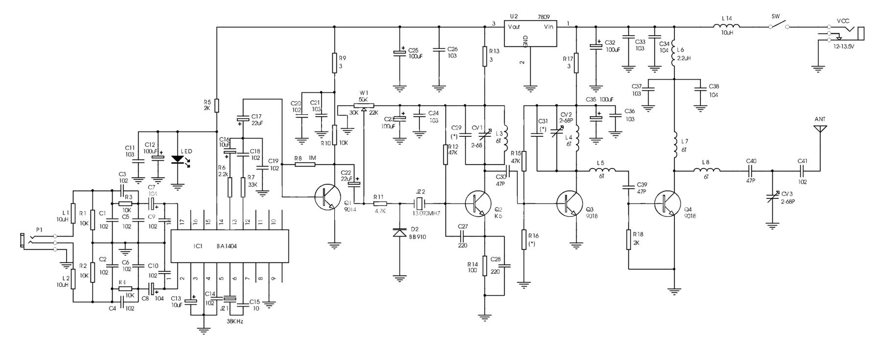
The following figure is the working principle diagram of the machine. The circuit is mainly composed of four parts: Power Supply circuit, stereo coding circuit, crystal oscillation circuit and RF amplification circuit; U2 and light-emitting diode LED and related resistance-capacitance components constitute the power supply circuit, of which U2 It outputs a stable 9V voltage for BA1404 and Q1Q2. In addition to being used as a power indicator, the LED also provides a stable working voltage of about 2V for BA1404. R5 is the current-limiting resistance of the LED. C25, C26, C32, C33, and C34 are power supply filter capacitors, and R5, R13, and R17 are power supply decoupling resistors, which can reduce interstage interference caused by the use of the same power supply. BA1404 and peripheral components form a frequency-modulated stereo encoding circuit, which does not use its internal high-frequency oscillation circuit, only uses it as a stereo encoder. R1, R2, R3, R4 and C1-C10 form the FM pre-emphasis and input matching network, which can effectively improve the frequency response effect with the de-emphasis network of the receiver. The two audio signals of L and R are input to pins 1 and 18 of BA1404 after pre-emphasis network and input matching network. The encoded audio signal is output from pin 14 and the pilot signal of 19KHZ is output from pin 13 for synchronous demodulation by the receiver LR signal. Q2 and the surrounding components form a crystal oscillation circuit, and its oscillation frequency is determined by the crystal oscillator JZ2. In this picture, it is 13.09MHZ. The audio coded signal and pilot signal output by IC1 are amplified by the amplifier circuit formed by Q1 and sent to the crystal oscillation circuit. The Q1 level can effectively increase the modulation frequency deviation. By selecting the varactor diode and crystal oscillator, the modulation frequency deviation can also be effectively increased. Q3 and Q4 form an RF power amplifier circuit, and Q2Q3 also plays the role of frequency multiplication and power amplification. By changing CV1CV2, the radio frequency frequency can be multiplied to 91.63MHZ (here is seven times the frequency), which just falls in the FM broadcast frequency band. Q4 works in category C and has a high launch efficiency. L8, C40, CV3, and C41 form a radio frequency filter and antenna coupling circuit. By adjusting CV3, high frequency waves can be effectively transmitted to the antenna, reducing harmonic components. The output power of the whole machine is about 1W, and the outdoor GP antenna is used to transmit in an open area.

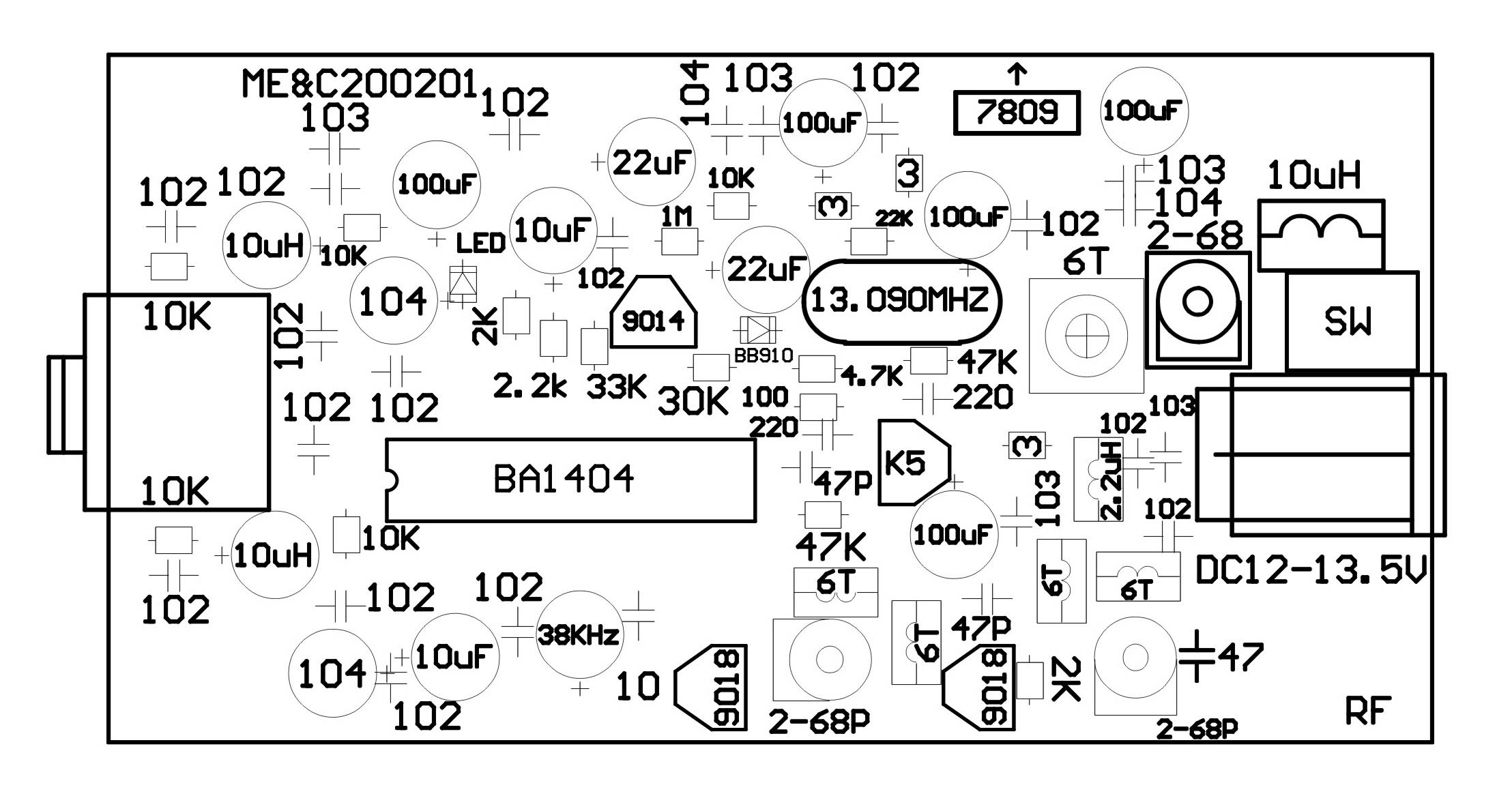
The following figure is the assembly drawing of the machine's circuit board. L1, L2, L6 use color-coded inductors, L6 should choose a color-coded inductor with a power of not less than 1 / 8W, and other inductance coils are all wound with a diameter of 0.51mm enameled wire on a 3.3mm drill bit, and the number of turns is as shown in the figure Mark. Q4 can also choose C2053 to make the output power higher. The working current of the whole board is about 200 mA. The DC power supply should select a DC adapter with an output current of not less than 500 mA and an input voltage of 12V. If the output power of the working power supply is not enough, it is easy to introduce hum, which will affect the working performance of the transmitter.

After all the components are welded and checked for correctness, connect the whip antenna or GP antenna, tune the field strength meter to 91.63MHZ, power on the test machine, adjust the CV1, so that the LC loop resonates at the N frequency of the crystal oscillator (here N = 7, That is 13.090MHZ x 7 = 91.63MHZ, within the FM88-108MHZ section), at this time the field strength meter indicates the maximum output, then adjust CV2 and CV3 to maximize the output field strength. The modulation frequency deviation of this circuit is slightly smaller than the modulation frequency deviation of ordinary radio stations, which shows that the sound output by the receiver is small, but it can meet the needs of normal normal reception. Adjusting W1 can improve the modulation frequency deviation, stereo separation and sound quality.
Hardware,gaming hardware,cabinet hardware,hardware fittings
Guangzhou Ruihong Electronic Technology CO.,Ltd , https://www.callegame.com