Human-machine interface design of medical data acquisition system based on ARM
This article refers to the address: http://
0 PrefaceThe medical data acquisition system can provide medical staff with first-hand data of patients in a timely and effective manner, which helps to strengthen the modern information management of the hospital and improve work efficiency. In terms of family health, it can meet people's health status in a fast-paced work life. In the daily use of the equipment, a good human-machine interface design will also save a lot of time and great convenience for the equipment users. This paper mainly uses LM3S3748 as the core, and adopts TFT liquid crystal as the display device of the system. The touch screen and the handle controller are used as the control devices of the system. The design method of the human-machine interface is introduced.
1 system hardware design
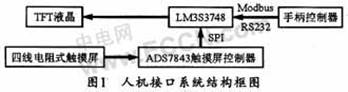
The system man-machine interface mainly includes TFT liquid crystal, touch screen and handle controller, and its structural block diagram is shown in Figure 1. Among them, TFT liquid crystal has good brightness, high contrast, strong layering and bright colors. Therefore, TFT liquid crystal is a good choice without considering power consumption. The touch screen uses the ADS7843 analog-to-digital conversion chip to sample the data of the touch screen, and then the sampled output value is subjected to a calibration procedure to obtain the physical coordinates of the touch screen. The controller of the controller adopts the Modbus protocol and controls the core board through the serial port.
1.1 Control unit
The control unit of this system can use TI's LM3S3748, supports ARM Codex-M3 core with 50 MHz frequency and 128 KByte FIASH, 64 KByte SRAM. Also integrated with USB HOST/DEVICE/OTG, sleep module, quadrature encoder, ADC, with dead band deletion, temperature sensor, analog comparator, UART, SSI, general purpose timer, I2C, CCP, DMA controller and other peripherals . In addition, the chip also has a driver library inside, which can better meet the system requirements.
1.2 LCD interface circuit
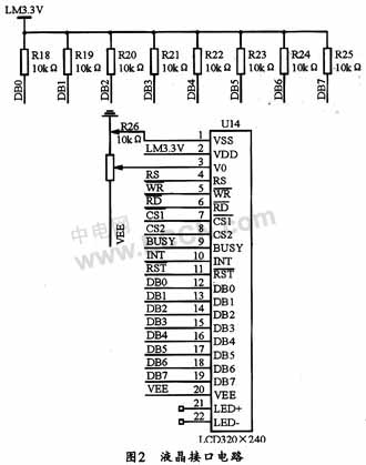
The LCD can be used with a 3.2-inch TFT (240×320) 260,000 color screen touch module. The module supports SD card and DATAFLASH, and supports 16-bit/8-bit mode. The module can realize 180 degree arbitrary rotation of the display screen, and has a touch screen and a touch control chip. The module defaults to the i8080 16-bit parallel interface and optionally an 8-bit parallel interface. Its liquid crystal interface circuit is shown in Figure 2.
1.3 touch screen control circuit
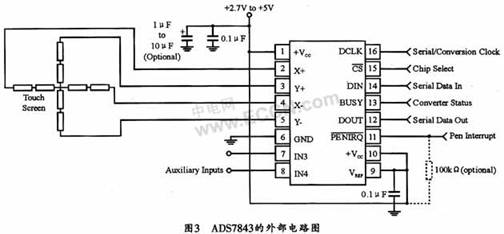
The ADS7843 used in the touch screen control chip is a 4-wire resistive touch screen conversion interface chip produced by TI. It is a 12-bit sampling analog-to-digital converter with a synchronous serial interface. The ADS7843 has two auxiliary inputs (IN3, IN4) that can be set to 8-bit or 12-bit mode.
The ADS7843 can input the touch signal to the A/D converter by connecting the touch screen X+, simultaneously turn on the Y+ and Y-drives, and then digitize the voltage of X+ to obtain the measurement result of the current Y position. Similarly, the X coordinate can also be obtained. Logical coordinates. After the logical coordinates of X and Y are obtained, the data is transmitted to the LM3S3748 through the SPI interface for data processing. The external circuit of its ADS7843 is shown in Figure 3.
1.4 RS232 serial communication circuit
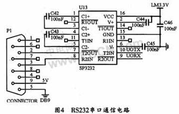
The RS232 serial port is mainly used for communication between the controller and the core board, which is similar to the keyboard interface in the human machine interface. They communicate via the Modbus protocol. Its RS232 serial communication circuit is shown as in Fig. 4.
2 system software design
2.1 touch screen software design
The ADS7843 has two modes of operation, single-ended reference mode and differential reference mode. It can also be selected for 12-bit or 8-bit conversion mode. This design uses a differential reference mode and a 12-bit conversion mode, namely:
WriteCharTo7843 (0xD0); send control word 10010000,
Use the differential mode + 12-bit conversion mode to read the X coordinate;
......
WriteCharTo7843 (0x90); send control word 11010000,
Use the differential mode + 12-bit conversion mode to read the Y coordinate;
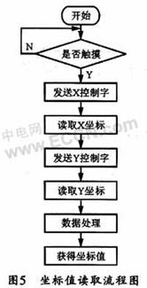
The CPU reads the coordinates using the interrupt method. When the screen is not touched, the PENIRQ pin of the ADS7843 is a high level output. When there is a touch action on the screen, the pin PENIRQ becomes a low level output. When the CPU detects the falling edge of this pin, The system enters the interrupt to read the coordinates. The flow of reading its coordinate values ​​is shown in Figure 5. When the CPU acquires the logical coordinates every time, it actually reads the X and Y coordinates 11 times respectively, and then stores the read logical coordinate values ​​into two arrays, and in the two arrays. The values ​​are sorted by bubbling so that they are arranged in order from small to large, and then the maximum and minimum two values ​​are removed, and the intermediate value is used as a reference, and the remaining values ​​are compared with the reference value to perform an absolute value difference calculation. A threshold can be set in the design (this threshold can be set to 5 according to the experiment). If the absolute value is greater than the threshold, discard this value, and finally sum the remaining values ​​as the final logical coordinate value. This is what the "data processing" in the flowchart does.
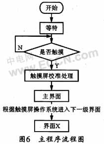
The main program flow chart in the system is shown in Figure 6. Among them, the touch screen calibration process uses a more general calibration algorithm. Since the resistive touch screen has a commonality, the voltage is linearly and evenly distributed. Therefore, as long as the proportional coefficient between the logical coordinate and the physical coordinate is obtained, the conversion between the logical coordinate and the physical coordinate can be realized. First, five physical coordinate points can be determined. And sequentially display it with "+" on the screen, and save its coordinate value with the array Set_x[4] (take the X coordinate as an example). The logical coordinate values ​​read during the calibration are stored in the array Read_X[3]. Finally, find the scale factor between the logical coordinates and the physical coordinates:
K1=(Read_x[1]-Read_x[0])/Set_X[1]-Set_x[0]);
K2=(Read_X[3]-Read_X[2])/Set_X[3]-Set_x[2]);
KX=(K1+K2)/2; 求 average the values ​​of the two operations to obtain the final X scale factor
After obtaining the scale factor, use the 5th point set as the reference point (Set_X[4]), so that the physical coordinates of any touch point can be found:
X=(ReadX-Read_X[5])/KX+Set_X[4];
Similarly, the physical coordinates of the Y axis can also be obtained.
2.2 Modbus communication protocol
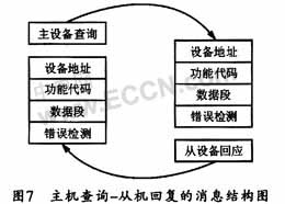
This system uses Modbus as the communication protocol between the controller and the core board. Modbus communication uses master-slave technology, that is, only one device (master device) can initiate transmission (query), other devices (slave devices) respond accordingly according to the data provided by the master device query, and the message structure of the host query and the slave reply is as follows. Figure 7 shows. The master device can communicate with the slave device individually or in a broadcast mode with all slave devices. If communicating alone, a message is returned from the device as a response; if it is queried by broadcast. Then do not respond. The Modbus protocol establishes the master device query format, including the device (or broadcast) address, function code, and all data error detection fields to be sent. The slave response message is also composed of the Modbus protocol, including the field to confirm the action, any data to return, and the error detection field. If an error occurs during message reception, or if the slave device cannot execute its command, the slave device will create an error message and send it as a response.
The Modbus protocol has two transmission modes, ASCII and RTU, but all devices on the same Modbus network must select the same transmission mode and serial parameters. This design uses RTU mode, that is, every 8 bit bytes in the message contains two 4 bit hexadecimal characters, so at the same baud rate, more data can be transmitted than ASCII. The message structure of the RTU mode is shown in FIG. 8. When the handle controller detects that a button has been pressed, the key code of the pressed key is sent to the core board through the serial port according to the structure of the RTU message frame. After receiving the information sent by the controller, the core board first performs the CRC check. After the verification is correct, the core board will operate according to the key code and respond to the handle controller. If the CRC check error occurs, the core board responds to the handle. The controller error message, after completing a communication, the system waits for the next communication.
3 Conclusion
The human-machine interface designed in this paper proves that its communication is stable and reliable through actual use, and the operation is simple and convenient, which can fully meet the requirements of medical data acquisition system. And the design is highly portable and can be improved according to the complexity of the system used. Therefore, it has a fairly wide range of uses.
Insulation PVC Fiberglass Sleeve
Insulation Pvc Fiberglass Sleeve,Pvc Coated Fiberglass Sleeve,Pvc Fiberglass Insulation Sleeve,Pvc Fiberglass Cable Sleeve
Longkou Libo Insulating Material Co.,Ltd. , https://www.liboinsulation.com