Implementation of electronic deferred detonator based on AVR
Electronic detonators are generally divided into three types: (1) electrically detonated programmable electronic detonators, the delay time is set at the blasting site according to the requirements of the blaster, and the initiation timing of the entire blasting system is programmed on site; (2) electric detonation Non-programmed electronic detonators, preset fixed extension time in the factory; (3) non-electrical detonation of non-programmed electronic detonators, which can be used to induce electronic delays with non-electric detonating devices such as detonating tubes or low-energy detonating cords, and then detonate Its fixed extension time is pre-set in the factory [1-2], and it is a great advantage to be able to easily form a simple, advanced detonation network that is an electronic deferred detonator. The program provides a design method for an electronic delay detonator that can be programmed online.
1 electronic deferred detonator
The electronic deferred detonator is a new type of electric detonator that can arbitrarily set and accurately realize the deferred ignition time. The essence is to replace the chemical deferred medicine and the electric ignition element in the ordinary electric detonator with a microelectronic chip, which not only greatly improves the delay. Accuracy, and control of the power to the ignition head, thus minimizing the delay error caused by the energy requirements of the ignition head.
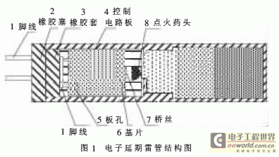
The structure of the electronic delay detonator that can be programmed online in this scheme is shown in Figure 1.

2 control circuit hardware design
The electronic deferred detonator uses a control circuit board to replace the chemical delaying agent in the ordinary electric detonator, which not only greatly improves the delay accuracy, but also reduces the blasting vibration hazard [1], and improves the anti-interference ability of the detonator through the control circuit.
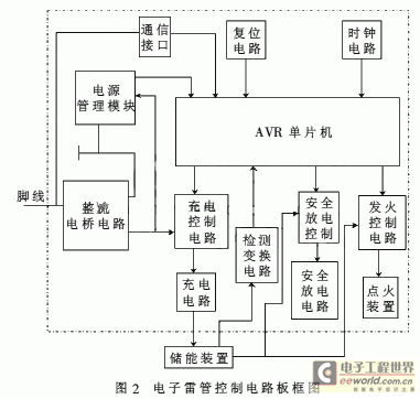
The block diagram of the control circuit board designed by this scheme is shown in Figure 2.

The control circuit chip is mainly composed of an intelligent control unit, a rectifier circuit, a charging control and charging circuit, a safety discharge circuit, a detection conversion circuit, a fire control circuit, a communication interface circuit, a power management circuit, and the like, which are composed of an AVR single chip microcomputer. Information exchange with the detonating device can be carried out via the communication network. If the ID of the electronic detonator sent by the receiving detonating device is the same as the ID stored in the storage unit itself, then receiving the charging command, the detection command, the setting delay time, the ignition command, etc. sent by the detonating device, and correspondingly according to the command word Reaction.
2.1 AVR microcontroller features
In this design, the intelligent control unit is required to work safely and reliably, and can quickly respond correctly after receiving the control command, and requires rich internal resources (such as requiring an on-chip integrated RC oscillator with multiple frequencies to be selected, and power-on automatically. Reset, serial communication interface, watchdog, ADC conversion and other functions), so that the peripheral circuit can be relatively simple, the system will be more stable and reliable design [3-4]. Under the premise of satisfying the above conditions, the price of the single-chip microcomputer is required to be low, and the price of the electronic detonator is controlled [3]. Only in this way can it be possible to put the electronic detonator into a large-scale production and use it widely.
The AVR MCU selected in this design can meet the above requirements. It adopts Harvard structure, streamlined instruction set, fast execution speed, integrated on-chip functional circuit required by this design, rich in internal resources, with E2PROM, PWM, RTC, SPI, UART, TWI, ISP, AD, Analog Comparator and WDT, etc., cost-effective [4-5].
2.2 control circuit function realization
The realization of the function of each function module of the control circuit is that after receiving the control command, the intelligent control unit responds by detecting the current state. For example, the energy storage device is charged: after receiving the charging control command, the smart unit outputs a control signal at the corresponding pin, so that the electronic switch in the charging control circuit is in a closed state, and the charging circuit stores energy to the outside of the control circuit chip. The device is charged. When the charging time is up, the intelligent control unit sends a control signal to turn on the electronic switch in the charging control circuit. After the charging is completed, the charging condition is converted into corresponding data through the A-port 10-bit AD conversion circuit of the AVR through the detection conversion circuit, and then sent back to the control management layer through the communication interface to make a correct decision.
Power cord can be used in wide range of industries. Home appliances, charging equipment, lighting, Gym appliance, computer, tool, pump, compressor, medical equipment, and so on. All products which are driven by electricity need a power cord.DC (direct Current) power cord is used to the applicance with lower voltage mostly, so safety requirement is less stringent.
DC Power Cord, power cable, DC cable, power connector
ETOP WIREHARNESS LIMITED , https://www.wireharness-assembling.com