The Construction of DPI Intelligent Network System Based on SDN/NFV
Pan Jie, Pei Zhuoning, Lin Peng, China Mobile Communications
Keywords: software-defined network; network function virtualization; DPI deployment; intelligent network system
1 Introduction
The traditional packet inspection technology only analyzes the contents of the IP layer below the 4th layer (source address, destination address, source port, destination port, and protocol type). DPI (deep packet inspection) also adds application layer analysis to identify Various applications and their content. As a flexible and effective service identification technology, DPI has been widely used in the network in recent years. According to different management and inspection requirements, you can choose to deploy the device in different network locations. This satisfies the requirements for detection of various levels of networks, but the cost for implementing multiple DPI technologies on different hardware platforms is high, and interoperability between applications is also difficult. Therefore, how to solve this problem has become a new research hotspot.
In recent years, as the research on SDN (Software define networking) and NFV (Network Functions virtualization) technology has matured, DPI has been decoupled from embedded network devices and converted into a standard server. The sharing function has become an effective way to solve the above problems. In this way, DPI only needs to be implemented on fewer machines, not only reducing energy consumption, but also effectively reducing the investment needed to deploy DPI. At the same time, interworking between different functions and DPI applications will also be effectively simplified.
2 Traditional DPI Deployment Scenarios
According to different traffic management and detection requirements, DPI devices can be deployed at different network locations, for example, in metropolitan area networks, provincial networks, backbone networks, or inter-network links and international exports. Different control positions, control requirements and methods are not the same. For example, the control over the backbone network is more demanding than the metropolitan area network control over the performance and throughput of the equipment. The following uses the inter-network links as an example to introduce common control methods.
2.1 concatenation
The serial connection method directly connects the P2P flow control device to the inter-network interconnection link as shown in FIG. 1 .

Figure 1 DPI device concatenation
This method is generally Layer 2 transparent transmission and does not require the configuration of an IP address. The serial connection method requires high performance and reliability of the equipment. The advantage of the cascading mode is that the traffic control effect is good. The token bucket and traffic shaping can be used to precisely control the traffic. However, there are defects that introduce fault points. In order to enhance the reliability of the equipment, an optical path protector is generally configured at the front end of the equipment so that the impact on the existing network is minimized when the flow control equipment needs to be upgraded or fails.
2.2 Parallel mode
The parallel connection method is to split the optical signal of the inter-network interconnection link to the DPI device by using the optical splitter, without affecting the data transmission in the original link, as shown in FIG. 2 .
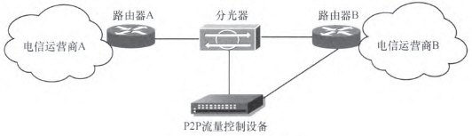
Figure 2 Parallel connection of DPI devices
DPI is deployed in parallel mode. The traditional traffic shaping and traffic control technologies are no longer applicable. Instead, it uses interference to control the flow. Interference packets are sent by the flow control device to the network. At the same time, the parallel connection adopts different control strategies for TCP (transmission control protocol) flow and UDP (user datagram protocol) flow. Because TCP is connection-oriented, the parallel connection control method is to send a reset or fin packet and remove the connection. For connectionless UDP, there is currently no effective control method for the parallel connection method. Commonly used is to send forged packets to degrade the communication quality.
2.3 Limitations of Traditional DPI Deployment
When choosing the access method, you can consider from the following aspects:
· Legal risk of equipment access;
· Coverage of flow control functions;
· Adaptability to encryption services;
· Accuracy of prosecution of particle size;
·The rationality of project deployment;
· Timeliness of prosecution.
Under normal circumstances, DPI deployment in series is a more reasonable and efficient method, and it is also a widely used deployment solution by operators. However, at present, operators' systems for network operations have increased the need for data and functional support for the deployment of DPI. This also forms a DPI deployment structure with rich layers but overlapping function sets. At the same time, it is influenced by factors such as the construction cycle of related application systems, integration vendors, investment budgets, and the external support capabilities of the DPI system itself. The current DPI system construction is highly repeatable. For example, in a user's service link environment, multiple application requirements are met. The scheme of unified splitting and independent deployment of their respective DPI systems, as shown in Fig. 3, has resulted in the coexistence of multiple DPI systems and brought about many aspects of redundancy.
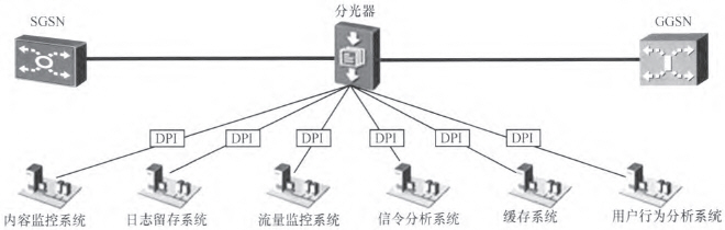
Figure 3 Multi-DPI System Parallel Access Topology
2.3.1 Repeated Investment
The coexistence of multiple DPI systems will lead to repeated purchases of the same functions, with low investment efficiency.
The functions and application modes of the DPI system are unified. Basically, the DPI system revolves around the contents of the parsed packet protocol field, the identification of service features, the collection of specified feature packets, and the implementation of traffic management policies issued by the management center. Each manufacturer's product is horizontally compared. The difference lies in the device architecture design, function implementation performance, and external support methods. Therefore, more than 70% of the functionality of a DPI system that is purchased repeatedly can be combined. This makes a huge waste of repetitive investments for DPI systems. Then, if you concentrate on investing and building a set of functions and excellent performance. Especially the DPI system with strong expansion and support capabilities. Even if the initial investment scale is large, long-term considerations will enable savings to be realized, thus achieving the highest overall benefits.
2.3.2 Multi-party maintenance
The coexistence of multiple DPI systems also increases the cost and difficulty of equipment and system maintenance.
Every manufacturer DPI system has its own maintenance system, operation interface and optimization methods. Even though the work intensity of operator management personnel can be reduced through outsourcing, collaboration, etc., the basic understanding of multiple systems, the guidance of outsourcing work, and the evaluation of the performance of collaborative partners will also cause great difficulties to management personnel. When the functional requirements of the upper application system develop, the functional upgrading and technical upgrading of the DPI system must also be promoted. The coexistence of multiple sets of DPI systems means that it is necessary to develop technologies for multiple vendors with different development capabilities and continuous development capabilities. Therefore, it will inevitably cause the system expansion/upgrade process to go long and uneven, and will bring maintenance and management to the system. Greatly troubled.
2.3.3 There is a hidden danger in the overall security of the network
Multiple DPI systems coexist with unnecessary introduction of system links, increasing the probability of system failure.
In order to provide raw traffic for multiple DPI systems, one-stage splitting is usually performed on the backbone link, and then an optical power amplifier is added to multiplex splitting schemes. Obviously, before the traffic was actually processed, the system had already introduced multi-stage optical splitters and optical amplifiers, which increased system instability. At the same time, due to the constraint of this mode, the number of available optical signals that can be tapped out eventually is limited, so the number of application systems that can obtain the original traffic is extremely limited.
3 Deploy DPI in SDN/NFV Networks
Through the above analysis, there are various problems in terms of economic aspects, management and maintenance, and security in the current complicated DPI deployment. This gave birth to a series of technical solutions that decoupled the DPI function from the traditional hardware. Here's how to achieve this through SDN/NFV technology.
3.1 SDN/NFV Technology and Its Impact on Network Development
SDN and NFV are promising new technologies emerging in the IT field. SDN abstracts network functions and service processing to separate the control and forwarding of network services. This technology shields the differences from the underlying network and liberates control of the network. NFV is based on SDN. It further decouples network functions from specific hardware devices and hosts them on general-purpose servers. Through abstraction of functions, this technology realizes full and flexible sharing of resources and further completes the intelligentization of the network system.
3.1.1 SDN Technology and Development
SDN technology is an implementation of network virtualization. Its core is the separation of network control and data. Centralized control of the network and programmable network applications are achieved through standardization, as shown in Figure 4. Based on the requirements for higher flexibility in the future network, SDN can centrally manage the control of network devices and define targeted policies as needed. Better complete the intelligence of the network. At the same time, due to the separation of the control layer and the data layer, SDN can operate data flow paths more intelligently through various upper layer applications to perform finer-grained rule matching and function optimization.
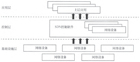
Figure 4 SDN architecture
3.1.2 NFV Technology and Development
NFV technology is a virtualization technology network that can complement SDN. It separates out network functions and business applications from dedicated hardware devices, and is hosted on general-purpose servers to complete the decoupling between hardware and software, as shown in Figure 5. NFV technology reduces the dependence of functions and services on dedicated equipment, provides conditions for more flexible management of network functions and business applications, and saves huge cost investment. NFV is a technology that is very suitable for operators. When SDN solves the problem of centralized global control and reasonable data forwarding in the global abstract view of the network, NFv solves the reasonable virtualization of network elements, reduces space and energy consumption, and combines them to achieve operations. Maximize the benefits of business.
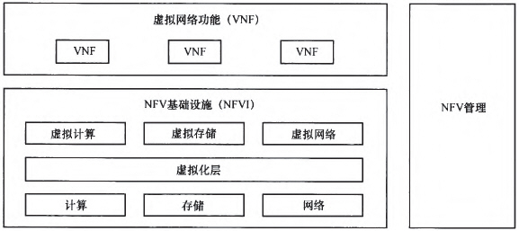
Figure 5 NFV architecture
3.2 DPI in SDN/NFV Architecture
According to the previous analysis, the traditional DPI deployment method is to embed DPI in various network devices such as Session Border Controller (SBC), Traffic Detection Function (TDF), and Gateway GPRS Support Node (GGSN). Based on the SDN/NFV-based virtualization capabilities, DPI services can be migrated from embedded network devices and become shared functions on managed standard servers. This approach reduces the total investment required for the DPI, because in this way the DPI only needs to be implemented on fewer machines (reducing the investment in fixed assets) and reducing energy consumption (reducing operating costs). In addition, interworking between different functions and DPI applications is no longer complicated because it is relatively easy to implement a consistent format for application IDs and metadata.
With SDN/NFV, DPI can not only reside in an existing location, but also realize more complex functions on an existing basis. For example, real-time traffic monitoring, intelligent aggregation of abnormal traffic, and centralized processing are implemented. You can also use machine learning and other methods to classify the data at the application level and analyze it in depth while meeting the higher throughput requirements. Get high accuracy.
3.3 Deploying DPI in SDN/NFV Networks
The SDN/NFV network architecture includes rich layers, and the DPI function can be embedded in several layers, as shown in Figure 6. These deployment scenarios simplify DPI management by using the infrastructure that provides DPI services to avoid merging DPI devices. The following is illustrated in several situations.
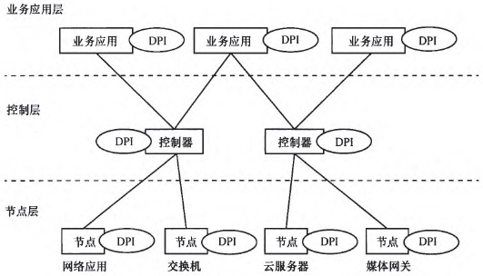
Figure 6 Hierarchy of DPI Embeddable
3.3.1 Node layer
Running DPI software on a network node is equivalent to putting the detection point at the forefront of the network, collecting information through it, and acting as the first barrier of the network. At this point, the SDN/NFV can act as a receiver and a decision maker, interact with the upper application, and instruct the obtained policy to the node or directly deliver a preset policy to the DPI software on the node. Such a setting can minimize the waiting time of DPI software and become the most rapid analysis source. However, this deployment method is also the most costly, and the number of instances of DPI software will increase with the number of nodes, resulting in a lot of consumption.
3.3.2 Control layer
Deploying DPI software in the controller can avoid the drastic increase of DPI instances caused by the increase in the number of nodes, thereby reducing overhead. At the same time, this deployment method can better apply network intelligence to control services and become a bridge between applications and nodes. At this point, the function of DPI will become an important part of the control decision. Equivalent to the entire "brain" of the SDN/NFV intelligent network, participates in the formulation of decisions and provides data for upper applications. Of course, this deployment method also has a corresponding problem: it will affect the network's scalability and analysis performance. This will require a higher distributed control architecture to reduce the impact of these issues.
3.3.3 Service Application Layer
Compared with the first two deployment methods, DPI software can be easily embedded in business applications. At this time, DPI software has become the main force of analysis of a large number of network data influx. At the same time, the data may experience a long communication time before reaching the DPI. For example, some data flows will reach the application layer through the node to the control layer, so that the analysis at this time is no longer strictly real-time, and will generate a certain delay. . In response to this situation, the effectiveness of its analysis can be fully exploited by extending the application. For example, adopt more targeted analysis strategies for different data sources, establish more complex and more effective analysis models, and mine deeper information in the data. This makes it an intelligent information provider for the network.
4 Conclusion
This article describes the existing traditional DPI deployment scenario, describes the status quo of the traditional solution and the problems faced, and describes the scheme of embedding the DPI program to build an intelligent network system based on SDN/NFV. SDN technology separates the control of the network from the forwarding of data. On this basis, the NFV technology is used to decouple the software and hardware to restructure the network. By introducing these two technologies into DPI deployments, they are virtualized to enable a lower-cost, smarter network architecture. The network system can maximize the scalability of the architecture, reduce repetitive consumption, and make it have a stronger ability to evolve to the future network.
At the same time, operators' intelligent networks based on SDN/NFV deployment and using DPI can provide new services and can better manage bandwidth while reducing investment and maintenance costs. Such an intelligent network system will better provide operators with more control over their networks, reducing the complexity of network functions running on general hardware platforms, and providing better applications for upper-layer applications through flexible data interfaces. The support of data support and management functions also created conditions for the launch of new services.
Solder Cup Power D-Sub Connector
ANTENK are a leader in the design, worldwide manufacture, and marketing of Solder Cup Power D-Sub miniature, D-Sub connectors designed for applications that require a rugged / robust I/O connector system.The Antenk POWER-D & Combo-D mixed contact d-sub connectors solder type are designed for rugged / robust applications where both power & signal are required from a single connection. Featuring [Solid-Pin" machined contacts, these connectors offer high reliability performance. These products are used in nearly all application markets, from control and measuring to telecommunications and computer applications. Owing to the combination of various contact types there are numerous possibilities of saving installation space and costs in the interface area. Antenk Power D solder cup connectors have a metal shell in both the plug and socket versions as well as stamped contacts with tin/lead in the solder cup area. They offers ease of termination and reliability.
ANTENK POWER SOLDER CUP D-SUB CONNECTOR
Select from a full range of premium cable mount Solder Cup D-Sub Connectors in standard & high density pin positions with either stamped or machined contacts.
ANTENK SOLDER CUP D-SUB MIXED CONTACT | MACHINED FEATURES
D-Sub Mixed Contact Connectors in 12 industry standard contact configurations: 3W3 | 3W3K | 5W1 | 5W5 | 7W2 | 8W8 | 9W4 | 11W1 | 13W3 | 13W6 | 17W2 | 21W1 | 21WA4
Available with 20 or 40 amp power contacts, 5 amp signal.
Allows signal, high current & high voltage in one connector.
Contacts are pre-loaded into the insulator.
ANTENK SOLDER CUP D-SUB MIXED CONTACT MATERIALS
Shell: Steel, nickel plated
Insulator: Glass-Filled Thermoplastic, U.L. 94V-O, Black
D-Sub Mixed Signal Contacts: Machined Copper Alloy, Full Gold Flash
D-Sub Mixed Power Contacts: Machined Copper Alloy, Full Gold Flash
Combo Power D-sub Connectors,Power D solder cup connectors, High Current D Sub Connector solder type, POWER-D Mixed Contact Connectors,Combo D-sub Connectors
ShenZhen Antenk Electronics Co,Ltd , https://www.coincellholder.com