Detailed analysis of Bluetooth technology
In the 10th century AD, a Danish king was born into a pirate family, unifying the divided Northern Europe (Norway, Sweden and Denmark) and becoming the king of the Viking Kingdom. The king's original name was Harald Gormsson. He loves to eat blueberries. He has the nickname "Harald Blåtand". The language translated from Scandinavia (Northern Europe) into English is "Harold Bluetooth".

In 1994, Ericsson set out to study a new type of short-range wireless communication technology, and in order to welcome this new technology to be introduced, Ericsson's nickname (Harold Bluetooth) named it. The original concept of Bluetooth technology is to replace the RS-232 standard cable (serial port) with wireless communication technology, so that various devices in the local space can be interconnected and coordinated. The deeds of the "Bluetooth" King are predicting the future of this short-range communication technology.
In 2014, V4.2 version of Bluetooth supports 6LoWPAN (IPv6 over LR-WPAN, IPv6-based low-speed wireless personal area network standard), making it easier for Bluetooth devices to access the Internet.
In 2016, Bluetooth 5.0 further improved the communication rate for low-power devices, and it can be combined with wifi to assist in positioning the devices in the room.
On July 19, 2017, Bluetooth technology fully supported the Mesh mesh network.
Throughout the development of Bluetooth technology, SIG is constantly pursuing the performance of wireless connectivity: EDR-Enhanced Data Rate (AMP), Sniff Subrating (BLE), Network Access (6LoWPAN, Mesh) and security. Pairing (SSP) to meet the needs of various applications for near field communication.
Originally, the SIG focused on "human-centric edge networks" for technological innovation. Today, the scope of Bluetooth application has gradually extended to all IoT edge scenarios: "Bluetooth Enhanced Rate Technology (BR / EDR)" applications from Wireless headsets have evolved into mouse and keyboard; "Bluetooth low-power technology" has been applied to watches and bracelets to discover the wearable market; and "Bluetooth Mesh networking technology" has targeted the entire (edge-domain) IoT market, including consumer segments. And the industrial sector.
From the latest networking architecture (Mesh networking), let us gradually see the Bluetooth technology alliance's anticipation of IoT communication and the understanding of the edge network.
Application layer model
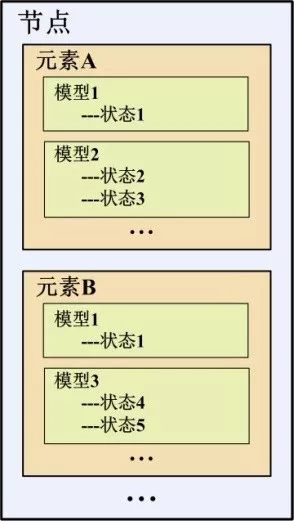
At the application level, the SIG encapsulates the functionality of Bluetooth devices in multiple layers: node-element-model-state.
(1) device (device) and node (node)
The role of the node (network role)
A device is an electronic terminal that has a Bluetooth function. After a device is added to the mesh network, it becomes a node. To join a mesh network, the device requires the authorization of the Provisioner in the network.
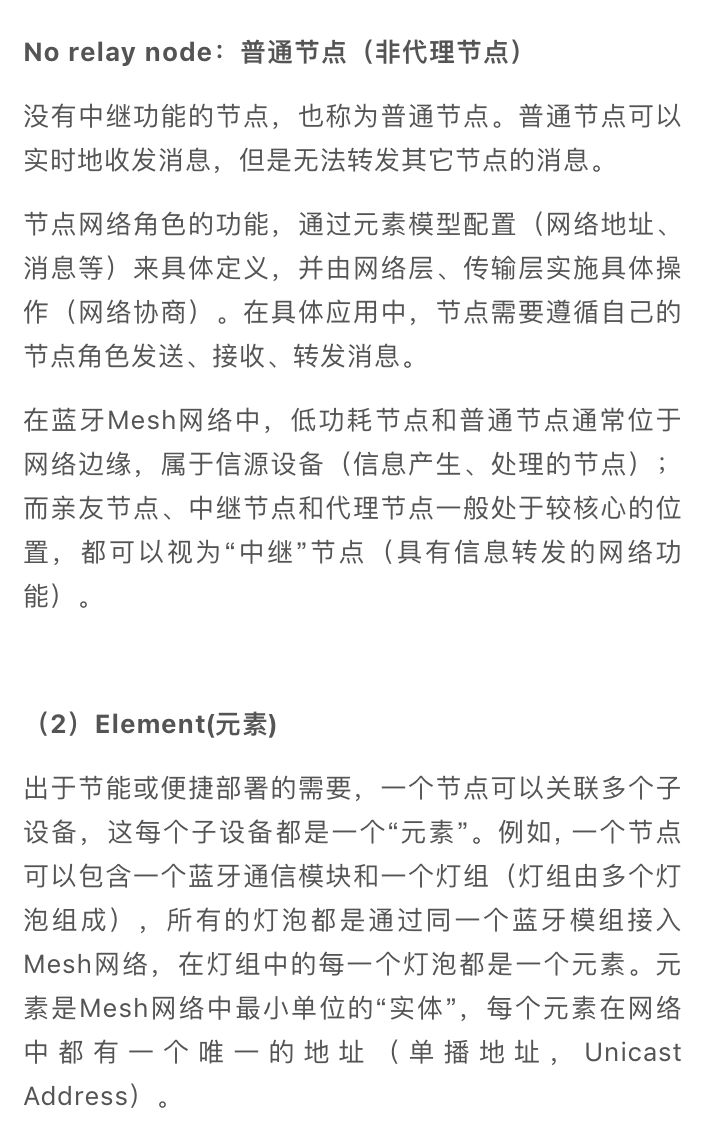
Relay node: relay node
In a mesh network, some devices are designated as "relay devices" to receive and forward Bluetooth Mesh messages through the broadcast bearer layer, which assumes the responsibility of extending network coverage. The relay node enables data to bypass the physical obstacles in the corridor through the "relay" of the wireless signal and deliver it to the destination device. The relay node needs ample power supply and has certain computing power. The Friend Node is a special relay node.
Proxy node: proxy node
The proxy node provides the GATT interface ("Generic Attributes", a communication protocol between low-power Bluetooth devices), so that the Bluetooth device can access the Bluetooth Mesh through the proxy node without the Bluetooth Mesh network protocol stack. The internet. The proxy node supports both the broadcast bearer layer and the GATT bearer layer for data packet transceiving. A proxy node is a special kind of relay node.
(3) Model and state
The model represents the behavioral functions of the elements in the node. An element must have at least one model, a function. Each model has a unique identifier (32 bits) that can be identified in the Mesh network.
The model has one or more "states". A state is a value of one or a specific type. A change in state represents a function performed on the model.
For example, the light has an on/off function. Among them, the light represents the "element" entity, and the function of on/off is the "model". The switch has two characteristics: "on", "off", which is the "state" of the lamp.
At the application level, a "node" is a "device" that accesses a Bluetooth Mesh network. It contains one or a set of "elements" (child devices), each element has some "model" (function), and each item The function is configured with one or a set of "status" parameters to indicate the action corresponding to this function.
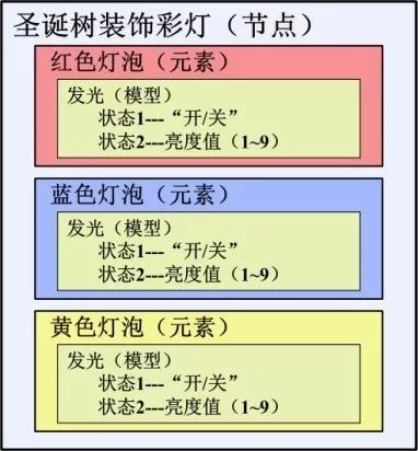
Whenever Christmas comes, the Christmas tree needs lighting decoration, and the lighting is usually a string of lights (made up of many different colored bulbs). This string of lights can be thought of as a "node." In order to create a Christmas atmosphere, the lights of each color in the string can be individually controlled as "Elements".
Each color of light has the function of illuminating as its "model". The model includes two state attributes: "on/off" state, brightness state. In this way, the Bluetooth Mesh network has the basis for dynamic control of the decorative lights.
Of course, if you need more dynamic effects, you can even configure each bulb as an element. However, doing so may "was" a lot of Bluetooth Mesh address resources (each element in the node will be assigned a unique unicast address). How to define and design the application is completely decided by the developer according to the product requirements. Bluetooth Mesh technology only provides a framework for node configuration.
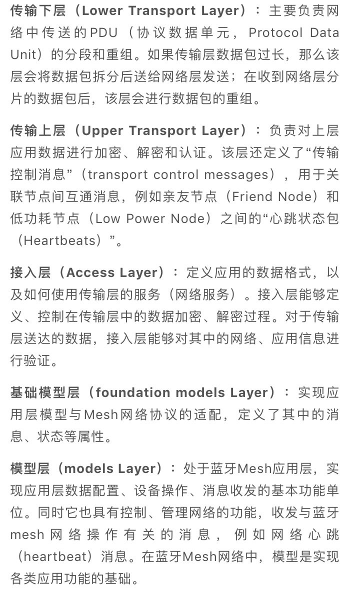
2. Network layer structure
The Bluetooth Mesh network is built on the Bluetooth Low Energy (BLE) architecture. The hierarchical architecture of the network is similar to the OSI 7-layer reference model: BLE layer-bearer layer-network layer-transport lower layer-transport upper layer- Access layer - base model layer - model layer.

BLE layer (Bluetooth Low Energy Layer): A low-power Bluetooth connection layer that implements wireless communication between nodes and is the basis for implementing Mesh networks.
Bearer Layer: Defines how to use the underlying BLE protocol stack to transport network PDUs (protocol data units). There are two types of actual bearers: the advertising bearer and the GATT bearer. By default, broadcast bearers are used to encapsulate Mesh network packets.
Network Layer: defines the address type and format of various messages, and completes network addressing and forwarding of data. The relay and proxy behavior of the node is implemented through the network layer.
3.96mm Wire To Board Connectors
3.96mm Wire To Board Connectors are avialable in different terminations and sizes intended for use on a variety of applications. These connectors provide power and signal with different body styles, termination options, and centerlines. To find the wire to board set required, click on the appropriate sub section below.
Antenk offers a wide variety of wire-to-board connector solutions that fit applications requiring high-power solutions or microminiature options.
3.96mm (0.156") Pitch Wire to Board Connectors delivering 7.0A and 600V per circuit in an industry-standard 3.96mm pitch, power application connectors are ideal for low- to mid-power wire-to-board and board-to-board applications
3.96mm Pitch Board-to-Wire Connectors are rated for up to 10 Amps max. when using 16 AWG wire. The locking mechanism provides a clear and tactile click that prevents incomplete mating and incorrect insertion. The pin header comes with a guide post to prevent reverse insertion on the PCB. The lance is part of the housing instead of being a part of the terminal, which prevents tangled wires during assembly. The wall structure between the contacts helps to isolate the contacts and prevents short circuits between contacts. The DF63 series is capable of being potted, up to 5mm. Glass-reinforced resin is used on the pin header to prevent solder cracks due to thermal contraction. Keying options prevent incorrect connections due to the use of multiple connectors on the same board. When using identical pin counts, two versions are available with different keying options.
3.96mm Pitch Board-to-Wire Connectors Features
Capacity to handle a maximum of 10A when using 16 AWG wire MAX 10A/pin AWG ♯16 7A AWG ♯18
A locking mechanism that ensures a secure and completed connection: The locking mechanism delivers a clear and tactile click the prevents incomplete mating
Prevents incomplete insertion of the crimp contact
Prevents incorrect insertion between different poles
Reverse mounting prevention to PCB: The pin header is equipped with a guide post to prevent reverse insertion on the PCB
Molded lance design: The lance is actually part of the housing instead of being a part of the terminal. This prevents tangled wires during assembly
Short-circuit prevention: The wall structure between the contacts helps to isolate the contacts and prevents short circuits between contacts
Capable of being potted, up to 5mm
Solder Crack prevention: Glass-reinforced resin is used on the pin header to prevent solder cracks due to thermal contraction
Keying options prevent incorrect connections due to the use of multiple connectors on the same board. When using identical pin counts, two versions are available with different keying options
Corresponds with 7.92mm pitch: Also corresponds with 7.92mm pitch with 2 or 3 pos. without pins
Pitch 3.96mm Wire to Board Connectors Specification
Pitch:3.96mm
Circuits:2-12P
Wire AWG:18-24
Current:7.0 A
Rated Voltage: 250V
Operate TEMP: -25℃~85℃
Resistance:1000/min(MΩ)
Withstanding Voltage:1500V
Max wire(Diameter) : 2.5
Pitch 3.96mm Wire to Board Connectors Features and Benefits
Smallest pitch for positive lock Wire-to-Board crimp system
Provides space savings for mounting other components
mating retention with low mating and unmating forces
Wide header variations to provides customers with many choices and design flexibility
Easy to mate and unmate
Space saving SMT Mounting that provides assembly and cost efficiencies
Automated assembly reduces manual labor processes
Pitch 3.96mm Wire to Board Connectors Application industry:
Automotive
Electronic modules
Consumer
Air conditionerMobile POS terminalsNotebook PCSmart metersTVsTelevisions UAVs/Drones
Industrial
Servo motor
Medical
Patient Monitor
This is not a definitive list of applications for this product. It represents some of the more common uses.
Board To Wire Connector,3.96Mm Wire To Board Connectors,3.96Mm Pcb Wire To Board Connector,3.96Mm Pin Wire To Board Connector,0.156" Wire To Board Connector
ShenZhen Antenk Electronics Co,Ltd , https://www.antenk.com