Hardware Implementation of LMS Adaptive Antenna Array in WCDMA
In CDMA, multiple access interference and multipath interference are important factors limiting system capacity and link quality. Adaptive antenna arrays can effectively reduce multipath effects through spatial domain filtering, suppressing multiple access interference and improving receiver output. Signal-to-noise ratio, which can improve system capacity, improve link quality, and increase cell coverage radius [1].
The adaptive antenna array performs beamforming by weighting the received signals of each array element, forms a main beam for the desired signal, and suppresses other interference signals as much as possible, thereby improving the signal to interference and noise ratio. The focus is on how to beamform. In these beamforming algorithms, according to whether training sequences are needed, it can be divided into a non-blind adaptive algorithm requiring pilot assistance and a blind adaptive algorithm based on inherent characteristics of signals. A blind adaptive array designed using only the inherent characteristics of the signal is computationally intensive, has a slow convergence, and is prone to divergence. The uplink symbols in the third generation mobile communication generally incorporate pilot symbols, and the pilot auxiliary signals can be used for better channel estimation and coherent reception. Combined with the technical specifications of WCDMA, the adaptive antenna array of this paper is proposed for this feature.
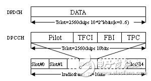
2. Adaptive array and LMS algorithmThe WCDMA uplink has two dedicated physical channels [2], namely a dedicated physical data channel DPDCH and a dedicated physical control channel (DPDCCH), which are used to transmit data and transmit control information, respectively. Each time slot in the DPCCH is formed by time-division multiplexing of pilot symbols, transmit power control bits (TPC), feedback indication information (FBI), and optional transport format combination indication (TFCI), as shown in FIG.
The adaptive antenna array utilizes the characteristics of the WCDMA uplink frame structure, and uses a spreading sequence of pilot symbols as a reference signal for updating the antenna matrix vector for each pilot slot of the time slot, and adopts an LMS beamforming algorithm for each chip. The weight vector is updated once, and the weight vector of the data segment is not updated, and the weight vector finally obtained by the same time slot is used directly. The calculation amount of the base station array processing is reduced, the convergence speed of the weight vector is greatly accelerated, and the stability of the system is improved, which is an effective receiving scheme. Since the weight of the adaptive array is only calculated in the pilot band, it is called a semi-blind adaptive array. Figure 2 is a schematic diagram of the adaptive array
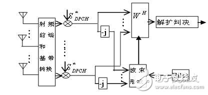
The signals received by the array elements are first down-converted to the baseband, and then each signal is separated by the complex scrambling code to separate the in-phase and orthogonal branches. By using the pilot signals transmitted on the uplink, the delay and phase of each signal can be compared. Accurate estimates. The estimation of the channel by the pilot symbols can control the beamforming weight vector. The weighting operation of this structure is chip-level.
X(n) is the signal received by the antenna array, W(n) is the weighting vector, e(n) is the calculation error, and μ(n) is the iteration step. The antenna array uses the spread spectrum sequence of the pilot symbol as the reference signal. Although the weight vector is updated only in the pilot frequency band of each time slot, and the data segment weight vector is not updated, the weight vector finally obtained by using the same time slot pilot frequency band is directly used. However, since the update of the weight vector is greatly accelerated by the chip, the convergence speed of the weight vector is sufficient to make up for the slow performance of the LMS algorithm on the performance of the system.
3, antenna array structureThe adaptive antenna array uses an 8-array antenna array for the uplink, and the operating frequency is 1.95 GHz. The antenna array structure is shown in FIG.
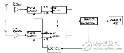
The RF channel of the antenna array consists of the MAX2641 low noise amplifier (LNA) and zero IF I/Q demodulator. The MAX2641 operates at 1.95GHz and provides a gain of around 14dB. The MAX2700 is a high-linearity direct quadrature downconverter operating at 1.8-2.1GHz. It uses an externally supplied local oscillator signal (LO) to directly demodulate a 1.95GHz signal to a baseband I/Q signal. The zero-IF architecture receiver does not have an intermediate frequency IF (Intermediate Frequency) in the system, thus avoiding image interference and saving the design cost of the image filter. At the same time, it eliminates the IF frequency conversion module and the mid-band pass filter, which greatly simplifies. The design of the entire receiver saves cost and is easy to be highly integrated and miniaturized.
The MAX2700 consists of five functional blocks: a low noise amplifier LNA, a quadrature downconverter, a baseband controllable gain amplifier, a baseband gain balance control circuit, and a bias circuit. The low noise amplifier LNA module is implemented by a single-ended input, gain-adjustable amplifier with a noise figure of 2.3dB at supply voltage +3V and a gain of 16dB during normal operation. The quadrature demodulation module directly downconverts the radio frequency signal to the baseband, and demodulates the I/Q two-way signal. The demodulation module includes: two double-balanced mixers with high linearity; a local oscillator optional multiplier module, a local oscillator orthogonal transform module, and a baseband I/Q buffer amplifier. The I/Q gain mismatch correction module is an enhancement to the structure of the direct downconversion receiver. The offset control circuit eliminates the DC offset of the gain-tunable amplifier through a built-in bias correction feedback amplifier. The MAX2700 operates from a low-voltage supply of 3V. The power does not exceed 0.5W during normal operation and 60μW in the shutdown state.
The baseband signal is sampled by 8 AD9288s, and each sample is sampled by four samples, quantized into 8 bits and input to the DSP for beamforming processing, and the weight is calculated. AD's AD9288 is a dual 8-bit high-speed analog-to-digital converter. The two ADCs can work independently. The integrated protection circuit and reference circuit are integrated inside and operate from a single power supply. Parallel output interface, compatible with TTL/CMOS format.
Using TI's TMS320C6701 as the baseband digital beamforming unit, TMS320C6701 is a new floating-point DSP chip with two multipliers and six arithmetic units integrated, using VelociTI super long instruction word (VLIW) structure, one instruction The word (256bit) combines eight 32-bit instructions to execute eight instructions in parallel in one clock cycle, with a peak computing power of 1336 MIPS, up to 1GFLOPS for single-precision operations, and 250 MFLOPS for double-precision operations. In beamforming, in the pilot band, the received signal of the Q channel is subjected to an LMS beamforming operation using the value of the pilot field known in advance as a reference signal. The calculated weight is used as the weight of the I signal. In the non-guided frequency band, the beamforming operation is no longer performed, and the weight directly follows the weight vector finally obtained by the same time slot pilot band. In addition, the DSP can communicate with the computer via the PCI bus. The antenna array can also be combined with a RAKE module to form a joint 2D-RAKE receiver to further improve the performance of the receiver.
4 ConclusionThe adaptive antenna is based on the new generation digital signal processor TMS320C6701, adopts high-speed A/D technology and zero-IF RF I/Q modem, has a simple structure and low complexity, and is suitable for use as a receiving antenna of a base station. The adaptive beamforming algorithm selected by the antenna array has low complexity and small computational complexity. Although it has the disadvantage of slow convergence, since the operation is chip-level, it can still converge in a shorter time.
Bubble Bag Machine,Dense Bag Cutting Machine,T-Shirt Bag Cutting Machine,Computer Automatic Bag Cutting Machine
Dongguan Yuantong Technology Co., Ltd. , https://www.ytbagmachine.com