What is the use of mimo technology?
The so-called MIMO, literally, is the abbreviation of MulTIple Input MulTIple Output. Most of what you see is that wireless network signals are sent and received synchronously through multiple antennas. Increase the data transfer rate.
However, the more correct explanation should be that the network data is transmitted synchronously through multiple antennas after multiple cuts. Because the wireless signal is in the process of transmission, in order to avoid interference, different reflection or penetration paths will be taken. The time to reach the receiver will be inconsistent. In order to avoid data inconsistency and can not be recombined, the receiver will have multiple antenna reception at the same time, and then use the DSP recalculation method to recombine the separate data according to the time difference factor, and then transmit the correct and fast data stream.
Since the transmitted data is divided and transmitted, not only the single data traffic is reduced, but also the transmission distance can be increased, and the antenna receiving range is increased. Therefore, the MIMO technology can not only increase the data transmission speed of the existing wireless network spectrum, but also does not need to additionally occupy the spectrum range. More importantly, it can also increase the signal receiving distance. Therefore, many wireless network devices that emphasize data transmission speed and transmission distance have begun to abandon the compatibility requirements of existing Wi-Fi alliances, and adopt MIMO technology to introduce wireless network products with high transmission rates.
The role of mimo technologyWhen the signal transmitted by the radio is reflected, multiple signals are generated. Each signal is a spatial stream. Systems using single-input single-output (SISO) can only send or receive one spatial stream at a time. MIMO allows multiple antennas to simultaneously transmit and receive multiple spatial streams, and is capable of distributing signals to or from different spatial orientations. The application of MIMO technology makes space a resource that can be used to improve performance and increase the coverage of wireless systems.
Increase channel capacity
Between MIMO access points and MIMO clients, multiple spatial streams can be simultaneously transmitted and received. The channel capacity can be linearly increased as the number of antennas increases. Therefore, the MIMO channel can be used to double the wireless channel capacity. Without increasing bandwidth and antenna transmit power, spectrum utilization can be multiplied.
Improve channel reliability
With the spatial multiplexing gain and spatial diversity gain provided by the MIMO channel, multiple antennas can be utilized to suppress channel fading. The application of multi-antenna system enables parallel data streams to be transmitted simultaneously, which can significantly overcome channel fading and reduce bit error rate.
MIMO technology can be roughly divided into two categories: transmit/receive diversity and spatial multiplexing. Conventional multiple antennas are used to increase the degree of diversity to overcome channel fading. Signals with the same information are transmitted through different paths, and a replica of multiple independent fading of data symbols can be obtained at the receiver end, thereby achieving higher reception reliability. For example, in a slow Rayleigh fading channel, one transmitting antenna is used for n receiving antennas, and the signal is transmitted through n different paths. If the fading between the individual antennas is independent, the maximum diversity gain can be obtained as n, and the average error probability can be reduced to, the average error probability of the single antenna fading channel is.
MIMO
For transmit diversity techniques, the gain of multiple paths is also used to improve system reliability. In a system with n transmit antennas for m transmit antennas, if the path gain between the antenna pairs is independently uniformly distributed Rayleigh fading, the maximum diversity gain that can be obtained is mn. Smart antenna technology also transmits the same data through different transmitting antennas to form shaped beams pointing to certain users, thereby effectively improving antenna gain and reducing interference between users. Broadly speaking, smart antenna technology can also be considered as an antenna diversity technique.
Diversity techniques are primarily used to combat channel fading. In contrast, fading characteristics in MIMO channels can provide additional information to increase degrees of freedom in communication. Essentially, if the fading between each pair of transmit and receive antennas is independent, then multiple parallel subchannels can be generated. If different streams of information are transmitted on these parallel subchannels, a transmission data rate can be provided, which is called spatial multiplexing. It should be particularly pointed out that in the case of high SNR, the transmission rate is limited in freedom, in which case n antennas are received for m transmitting antennas, and the antenna pairs are independently and uniformly distributed Rayleigh fading.
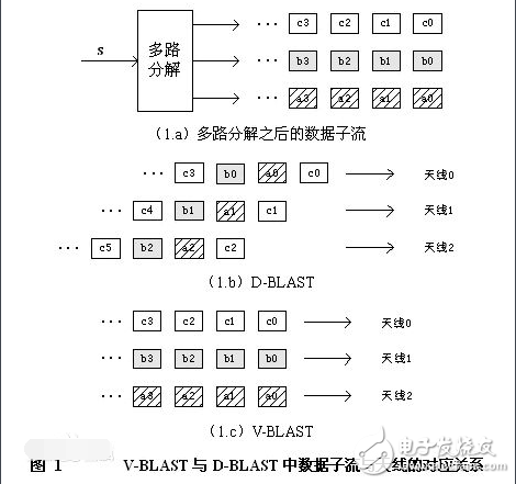
According to the correspondence between the sub-data stream and the antenna, the spatial multiplexing system is roughly divided into three modes: D-BLAST, V-BLAST, and T-BLAST.
D-BLAST
D-BLAST was first proposed by Gerard J. Foschini of Bell Labs. The original data is divided into several substreams, each of which is encoded separately, but the substreams do not share information bits, and each substream corresponds to an antenna, but the correspondence periodically changes, as shown in the figure. As shown in 1.b, each of its layers has a diagonal shape in time and space, called D-BLAST (Diagonally-BLAST). The advantage of D-BLAST is that the data of all layers can be sent to the receiver through different paths, which improves the reliability of the link. The main disadvantage is that a part of the space-time unit is wasted due to the diagonal shape of the symbol in space and time, or the redundancy of the transmitted data is increased. As shown in Figure 1.b, at the beginning of data transmission, some space-time units are not filled with symbols (corresponding to the blank part in the lower right corner of the figure). In order to ensure the space-time structure of D-BLAST, there must be a part at the end of the transmission. The space time unit is wasted. If the digital communication in the burst mode is adopted, and the length of one burst is greater than the transmission interval of M (the number of transmitting antennas), the smaller the length of the burst, the more serious this waste is. Its data detection needs to be done layer by layer, as shown in Figure 1.b: first detect c0, c1 and c2, then a0, a1 and a2, then b0, b1 and b2...
V-BLAST
Another simplified BLAST structure was also first proposed by Bell Labs. It adopts a direct antenna-to-layer correspondence, that is, the encoded k-th substream is directly sent to the kth antenna, and the period change of the correspondence between the data stream and the antenna is not performed. As shown in Figure 1.c, its data stream is a continuous vertical column vector in time and space called V-BLAST (VerTIcal-BLAST). Since the data substream in V-BLAST has a simple correspondence with the antenna, in the detection process, as long as the antenna is known from which antenna the data is from, the detection process is simple. (figure 1)
T-BLAST
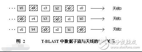
Considering the advantages and disadvantages of D-BLAST and V-BALST modes, a space-time coding structure different from D-DBLAST and V-BLAST is proposed: T-BLAST. Such documents are mentioned separately in the literature. Its layers are threaded and spatially distributed as shown in Figure 2. After the original data stream is demultiplexed into several substreams, each substream is sent by the corresponding antenna, and this correspondence periodically changes. Unlike the D-BLAST system, there is not only one in the initial stage of transmission. The root antenna transmits, but all antennas transmit, so that the space-time distribution is much like V-BALST from a transmission time interval, but the sub-data stream corresponds to the antenna in different time intervals. The relationship changes periodically. A more common T-BLAST structure is that this correspondence is not a periodic change, but a random change. Thus, T-BLAST can not only make all sub-streams share spatial channels, but also has no waste of space-time units, and can be detected using the V-BLAST detection algorithm.
MIMO
Principle of mino technologyOFDM is a multi-carrier digital modulation technique that encodes data into a radio frequency signal. Unlike conventional single-carrier techniques, such as AM/FM (Amplitude Modulation/Frequency Modulation), which transmit a single signal with a single frequency at a time, OFDM simultaneously transmits multiple high-speed signals over a specially calculated orthogonal frequency. This result is as efficient as the use of bandwidth in bursts of noise and other interference.
The traditional FDM (Frequency Division Multiplexing) theory divides the bandwidth into several subchannels, with a guard band in the middle to reduce interference, and they simultaneously transmit data. For example: cable TV systems and analog radio broadcasts, the receiver must be tuned to the appropriate station.
OFDM systems require much less bandwidth than traditional FDM systems. Due to the use of interference-free orthogonal carrier technology, no guard bands are required between individual carriers. This makes the use of the available spectrum more efficient. In addition, OFDM technology can dynamically allocate data on subchannels. To achieve maximum data throughput, multi-carrier modulators can intelligently allocate more data to sub-channels with less noise.
The application of OFDM to overcome inter-symbol and adjacent-channel interference techniques dates back to the mid-1960s. However, the practical application of OFDM has long been limited by the speed and efficiency of fast Fourier transformers. Today, the maturity of high-performance PLD (Programmable Logic Device) technology has created the current application of OFDM.
Modern single-carrier modulation methods such as integrated amplitude modulation (QAM) or integral phase shift keying modulation (QPSK) combine basic amplitude modulation, frequency modulation, and phase modulation techniques to provide higher noise rejection and better system throughput. The use of increased complex modulation techniques requires high performance digital logic, but also allows system builders to achieve higher signal-to-noise ratios and spectral efficiency close to the first-in-far limit.
The OFDM structure can be divided into a forward error correcting encoder, an interleaver, a constellation map, a serial-to-parallel converter and a receiving portion of the inverse fast Fourier transformer, a parallel-serial converter, and a cyclic prefix according to an OFDM data processing flow. Insert, shape finite excitation response filter, digital-to-analog conversion and other modules.
OFDM modulation uses channel coding to suppress multipath effects, data symbols are mapped onto a corresponding constellation (like QPSK, QAM), and the resulting I and Q values ​​are stored in the buffer and the inverse fast Fourier transform (IFFT) is applied. The IFFT is modulated on a quadrature carrier. The data is ready to be sent and serialized in addition to a multipath effect plus a cyclic prefix. The processed signal is sent to the antenna and sent out.
1. functional module
(1) Forward Error Correction (ForwardErrorCorrecTIon)
The channel coding uses a Reed-Solomon code, a convolutional error correcting code, a Viterbi code or a TURBO code.
(2) Interleaver
The interleaver is used to reduce burst errors in the data channel, and the interleaved data is mapped to a corresponding constellation through a serial to parallel converter.
(3) constellation diagram
Multi-carrier OFDM is considered to be superior to N independent sub-bands modulated by a single carrier. The constellation maps the symbols to the corresponding constellation points. This process produces IQ values ​​that are filtered and sent to the IFFT for transformation.
(4) Buffering
  Used to store the IQ value before being sent to IFFT. The IFFT can quickly and efficiently apply the discrete Fourier transform function and mathematically generate orthogonal carriers for OFDM transmission. The core of OFDM is IFFT. IFFT modulates each subchannel to a high precision orthogonal carrier. The channelized data is injected into a parallel string buffer, and the serial data is prepared for transmission by DAC conversion.
(5) parallel to serial converter
Used to convert parallel data to serial data.
(6) Cyclic prefix
The cyclic prefix creates a guard band for a single OFDM symbol individual that is dropped in the SNR edge loss to greatly reduce ISI. A Shaped Finite Excitation Response Filter (ShaperFIRFilter) is used to shape the signal.
Single Phase Portable EV Charger
Single Phase Portable Ev Charger,Portable Electric Car Charger,Portable Electric Vehicle Charger,Portable Ev Car Charger
Yangzhou JERI New Energy Co., Ltd. , https://www.jrevcharging.com