Lightning protection design solution for satellite antennas
Communication satellites for television/broadband service broadcast signals mainly use two operating frequency bands, namely C and Ku. The C-band has a frequency range of 4.0 GHz to 8.0 GHz, while the Ku-band has a frequency range of 10.7 GHz to 18.4 GHz.
Within these two bands, each satellite is assigned a dedicated uplink and downlink frequency. The C-band downlink frequency is 3.7 GHz-4.2 GHz, and the upstream frequency is 5.925 GHz-6.425 GHz. The downlink frequency of the Ku band is 10.7 GHz - 12.75 GHz, and the upstream frequency is 17.3 GHz - 17.8 GHz.
In order to utilize the available frequency bands of satellite broadcasting as efficiently as possible and to accommodate more channels in a given frequency band, at a certain frequency, the transmitted signals can be simultaneously polarized vertically and horizontally, or right-handed and left-handed circularly.
The designer of the lightning protection circuit must ensure that this function is complete under all circumstances.
Low noise module (LNB)The LNB is a low noise module placed at the focus of the satellite dish (parabolic cylinder) to provide the following functions:
1. The incident signal is downconverted from GHz to the 910 MHz-2150 MHz (Europe) frequency range, also known as the "initial conversion signal." This conversion allows the signal to be transmitted to the receiver over an inexpensive coaxial cable.
2. Signal amplification with good noise figure. The LNB uses a built-in low noise amplifier to increase the level of the initial converted signal.
3. Choice of vertical or horizontal polarization.
4. When the LNB "receives" a 22 kHz single-frequency signal (tone), it selects the operating frequency band by switching its internal oscillator from the low frequency band to the high frequency band. For example, the local oscillator (LO) frequency is changed from 9.75 GHz to 10.6 GHz (C-band, LO frequency is 9.75 GHz; Ku-band, LO frequency is 10.6 GHz).
5. Various functions based on PPM encoding of 22 kHz single frequency signals are discussed later in this article.
Polarization selectionPolarization is a method of specifying the direction of signal transmission. It enhances beam strength.
The signals emitted by satellites can be polarized in four ways: linear polarization (horizontal or vertical) or circular polarization (left or right). Therefore, satellites can propagate H and V or LH and RH polarized signals at a certain frequency.
The "universal" LNB changes the polarization according to the voltage it receives from the receiver. In general, one type of antenna is only suitable for both 13V and 18V signal voltages. The 13V signal (ranging from 11.5 to 14V) uses vertical polarization or right circular polarization (RHCP). The 18V signal (ranging from 15.5 to 21V) uses horizontal or left circular polarization (LHCP). In addition, a 1V voltage from the receiver can be added to any of the above voltages to compensate for voltage losses in the coaxial cable.

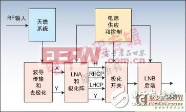
Figure 1 OMNI-LNB architecture


Figure 3 modulation scheme

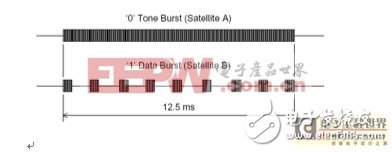
Figure 4: Schematic diagram of the timing of the single-frequency train control signal

Figure 5: IEC 61000-4-5 current waveform
22 kHz single frequency signal and DiSEqC codingLNB not only needs to choose the polarization mode, but also must select the working frequency band. Each receive band is divided into two bands: the low band (10.7-11.7 GHz) and the high band (11.7-12.75 GHz). This can be done with a 22 kHz single frequency, that is, a 22 kHz pulse position modulated signal with an amplitude of about 0.6V is superimposed on the LNB DC power rail. Its coding scheme allows for more complex functions to be performed by remote circuits. Traditionally, when other encoding functions do not require a 22 kHz single frequency, the operating frequency band can be selected simply by determining whether the single frequency occurs by changing the local oscillator frequency of the LNB.
The complex encoding of a 22 kHz single-frequency wave train can be implemented using a more sophisticated communication protocol called the Digital Satellite Equipment Control (DiSEqC) standard. Developed by the European Telecommunica TIon Satellite Organiza TIon, this open DiSEqC standard is a widely accepted global standard for communication between satellite receivers and satellite peripherals.
The 22 kHz oscillator must be a single frequency signal generator with a specific rise and fall time. Its waveform is a quasi-square wave (flat top sine wave). The frequency tolerance as a function of line and temperature is 2 kHz.
Need lightning protectionThe LNB is powered remotely via a satellite set-top box. The IF signal is transmitted from the LNB to the receiver over the same coaxial cable and the power of the receiver is transmitted to the LNB. A dedicated LNB voltage regulation chip produces a DC voltage of 13V to 18V. Any damage from the lightning cable to the coaxial cable or antenna can damage the transformer, which can generate large inrush currents and surge voltages.
According to the IEC 61000-4-5 standard, this surge effect can be simulated.
In the event of a lightning strike, the inrush current input at the LNB voltage regulation chip ranges from 250 A (when subjected to a 3kV lightning strike) to 500A (a 6kV lightning strike). And this IC can't withstand such high energy.
In order to comply with IEC specifications and protect the LNB voltage regulation chip from any damage from lightning strikes, a dedicated optimized protection device is required in front of the chip.
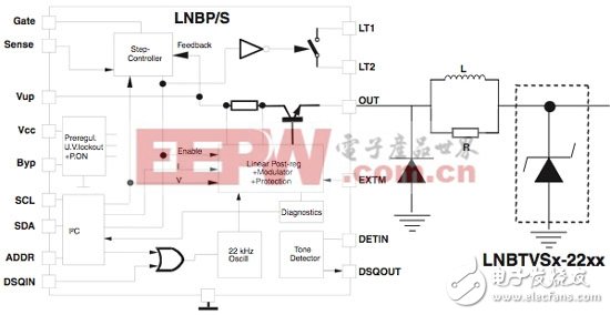
Design solution parametersA solution based on the segmentation method needs to be found to provide the most suitable protection device, so that the various LNB voltage regulation chips have the largest absolute rating. Depending on the LNB voltage regulation chip type used in the application, as well as the lightning surge test results, a different solution can be taken to optimize the cost and robustness of the overall solution. Special considerations should be given to the following features when choosing a solution. Figure 6 shows the +4 kV surge test (standard IEC61000-4-5 with a series resistor). For a trade-off between the cost of the LNB voltage regulation chip and lightning protection, see the application example diagram (Figure 7).

Figure 6: Surge Test + 4 kV

Figure 7: Schematic diagram of the application example

Table 1 Frequency band and polarization mode selection table
Silicone Sheets,Silicone Gel Sheets,Thin Silicone Sheet,Silicone Sheet
Nantong Boxin Electronic Technology Co., Ltd. , https://www.ntbosen.com