How to connect the wires and wiring of the load cell to common problems? -Huaqiang Electronic Network
The elastic body (elastic element, sensitive beam) is elastically deformed under the action of external force, so that the resistance strain gauge (conversion element) attached to the surface is also deformed along with it, and the resistance value of the strain gauge will change after the deformation of the strain gauge. Large or small), and then the corresponding measurement circuit converts this resistance change into an electrical signal (voltage or current), thereby completing the process of converting the external force into an electrical signal.
How to load the load cell:
Firstly, determine the power supply positive, negative power supply, feedback positive, negative feedback, positive signal and negative signal of the sensor interface on the display. If it is a 6-wire transmitter, the two sets of lines with the smallest sensor resistance are positive and positive feedback. Negative power supply, negative feedback, load the sensor after receiving the monitor, measure the voltage value of the other two wires (millivolts) is connected to the display signal positive, negative connection display signal is negative; if it is a four-wire value, the power supply of the display needs to be positive Short-circuit with the feedback, short-circuit between the negative and negative feedback of the power supply, measure the four wires of the sensor with a multimeter, wherein the two of the largest resistance values ​​are the power supply, and the other two are the signals;
According to the origin of the sensor, we can use the color of the lead to judge. We usually red for the power supply, black for the power supply, yellow for the positive signal, and white for the negative signal.
The load cell can be used with two different input and output wiring methods: one is a four-wire connection and the other is a six-wire connection.
The load cell of the four-wire system has no special requirements for the secondary instrument, and it is convenient to use, but when the cable is long, it is easily affected by factors such as fluctuations in the ambient temperature.
Load cell four-wire wiring diagram:
The load cell of the six-wire system requires a secondary input instrument with a feedback input interface. The scope of use has certain limitations, but it is not susceptible to environmental temperature fluctuations and other factors, in precision measurement and long-distance measurement. It has certain advantages.
Load cell six-wire wiring diagram:
In the weighing equipment, the four-wire sensor is used more. If the six-wire sensor is to be connected to the four-wire sensor device, the feedback positive and the excitation can be connected together, and the feedback negative and the excitation negative are connected together. One thing to note about the signal line is that the corresponding output signals for red and white on the two types of sensors are different.
Common wiring problems with load cells:
What is the difference between the power supply wiring (EXC-, EXC+) and the sensor line (SENSE-, SENSE+) in the load cell wiring?
1. The sensor outlet has 4 lines and 6 lines;
2. The wiring of the module or weighing transmitter is also available in 4 wires and 6 wires;
Whether you want to connect 4 or 6 lines depends on how your hardware requirements are. The principle should of course be:
If you can connect 6 lines without 4 lines, you must connect 4 lines to short.
The general load cells are all six-wire. When connected to a four-wire system, the power supply wiring (EXC-, EXC+) and the sensor cable (SENSE-, SENSE+) are shorted.
The sensor line (SENSE-, SENSE+) is not the output signal wiring of the sensor! !
The output signal wiring is SIG+ and SIG-?
EXC+ and EXC- supply power to the load cell, but due to the line loss between the weigh module and the sensor, the voltage actually received by the sensor is less than the supply voltage. Each load cell has a mV/V characteristic, and its output mV signal is closely related to the received voltage. SENS+ and SENS- are actually a high-impedance loop in the weighing module, which can actually weigh the module. The received voltage is fed back to the weighing module. Assuming EXC+ and EXC- are 10V, line loss is 0.5V, sensor is 2mV/V, in fact, the sensor output maximum signal is (10-0.5)*2=19mV instead of ?20mV. At this time, 19mV will be used as the maximum range inside the weighing module, provided that the sensor must feed back the actual voltage to the weighing module through the feedback loop. Shorten EXC+ and SENS+ on the weighing module, and short-circuit EXC- and SENS-, only when the distance between the sensor and the weighing module is close, and the voltage loss is very small, otherwise there is error in the measurement.
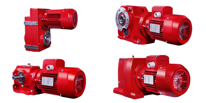
FC parallel shaft helical gear reducer
Product specifications:27-157
Transmission ratio:3.77~281.71
Input power: 0.12~200kW
Output torque:3.5~22500N.m
RC in-line helical gear reducer
Product specifications:7~167
Transmission ratio:1.3~289.74
Input power: 0.09~160kW
Output torque:2.8~22500N.m
KC helical-bevel gear reducer
Product specifications:37~187
Transmission ratio:5.31~179.86
Input power: 0.12~200kW
Output torque:10~62800N.m
SC helical-worm gear reducer
Product specifications:37~97
Transmission ratio:6.8~288
Input power: 0.12~22kW
Output torque:11~4550N.m

Helical Gear Reducer,Bevel Reducer,Bevel Helical Reducer,Helical Speed Reducer
Ningbo Biote Mechanical Electrical Co.,Ltd , https://www.biotept.com