Lcr digital bridge working principle and use method _lcr digital bridge role introduction
Digital bridges are instruments that can measure inductance, capacitance, resistance, and impedance. This is a traditional habit. The earliest impedance measurement uses a true bridge method. With the development of modern analog and digital technologies, it has already been eliminated. This measurement method, but the name of the LCR bridge has been used ever since. If it is a LCR bridge using a microprocessor, it is called an LCR digital bridge. The average user also calls these: LCR tester, LCR bridge, LCR meter, LCRMeter and so on.
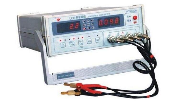
Structure of LCR digital bridge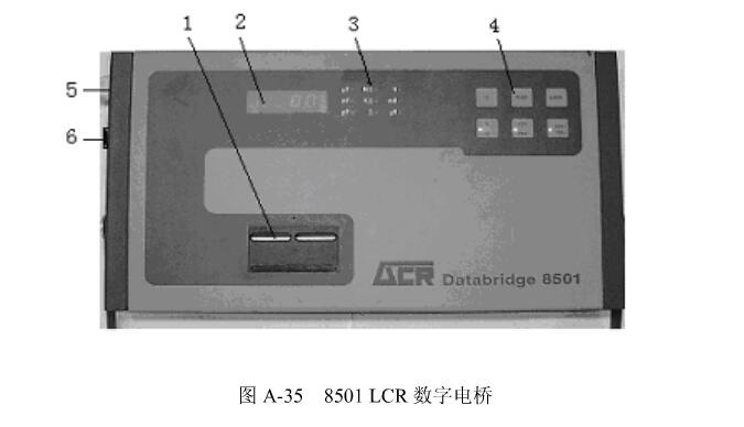
1. Test clip: the device under test is thus connected;
2. Reading display: The measured value is displayed by a 4-digit 7-segment LED display;
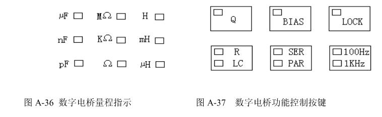
3. Range indication: display the unit to be measured (the small square on the right side of the unit is the red LED indicator);
4. Function control button: The measurement control button is composed of 6 function keys (the small square in each button is the red LED indicator);
5. Power input socket;
6. Power switch.
Lcr digital bridge working principleThe measurement object of the digital bridge is the parameters of the impedance component, including the AC resistance R, the inductance L and its quality factor Q, the capacitance C and its dissipation factor D. Therefore, the digital bridge is often referred to as a digital LCR meter. The measurement frequency is from the power frequency to about 100 kHz. The basic measurement error is 0.02%, which is generally around 0.1%.
The principle of the digital bridge is shown in the figure. In the figure, the DUT is the device under test, its impedance is represented by Zx, and Rr is a standard resistor. The switch can measure the voltages Ux and Ur of the two, respectively, so there is the following formula:

This formula is a phasor relationship. If a phase sensitive detector (PSD) is used to measure the in-phase component and the quadrature component of Ux and Ur corresponding to a certain reference phasor, respectively, and then convert it into a digital quantity by an analog-to-digital conversion (A/D), and then The complex value and the reactance value of the measured impedance Zx are obtained by a computer performing a complex operation.
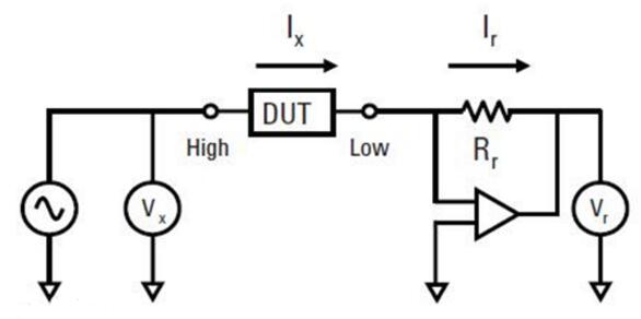
Balanced bridge test principle
As can be seen from the circuit and working principle in the figure, the digital bridge only inherits the traditional name of the bridge. In fact, it has lost the form of the traditional classic AC bridge, but at a higher level back to Ohm's law-based ammeter, voltmeter circuit and principle.
How to use LCR digital bridge1, power up
First connect the power cable with the IEC end to the IEC socket on the left rear of the bridge, and the other end to the appropriate power socket, and move the boat switch on the left rear of the bridge, even if the bridge is energized. When power is applied, the display, range, and function indicators light up. The bridge can be automatically placed in the inductor and capacitance measurement files, parallel equivalent and 1KHz frequency state. Under normal circumstances, the internal circuit can be stabilized after a few seconds of power-on, and measurement can be performed.
2. Access method of the tested component
(1) Generally, the components of the radial lead can be directly inserted into the combined test clamp, and the components of the special flexible lead should be connected by the clamp clutch, which is located directly under the test clamp.
(2) When accessing the axial lead components, in order to avoid twisting the leads, an axial adapter can be used. First, insert the two fittings into the two ends of the test clip, and then adjust the spacing to the position suitable for the component measurement, and then The axial lead elements are inserted into the accessory clips at both ends.
(3) Where the axial adapter must be fairly fixed, such as when measuring a large number of similar components, a support plate is required. Install the support plate: first adjust the axial adapter to the appropriate position, then suspend the support plate over the axial adapter, let each axial adapter pass through the slot on the support plate, and place the support plate Align the fixing screws with the screw holes on the bridge panel and finally tighten the screws. Note: It is not easy to screw the screws too tight during installation.
Note: Although the bridge can protect the charging capacitor access test, it is better to measure the charging capacitor after discharging it with a suitable resistor.
Note reading display and range indication during use(1) The measured value is displayed on a 4-digit 7-segment LED display. The decimal point is automatically shifted, and in some measurements the measured value will not be displayed in all 4 digits. This is because the bridge has the identification that the display bits are stable, and those that confirm the unstable bits will not be displayed.
(2) Under the measurement conditions that the bridge can provide the basic accuracy of ±0.25%±1 words, the readings are usually displayed in all 4 positions. The range indicator is on the right side of the reading display. The bridge can be automatically displayed on a unit based on the actual value of the component under test. Note: Since the Q value is dimensionless, the range indicator LED will not illuminate when the Q value is displayed.
(3) Low accuracy prompt When the bridge shows that the basic accuracy cannot be reached, the bridge still measures, but the corresponding unit LED in the range indicator flashes once per second to indicate that the measurement is low precision. At this point, if the control function is properly changed, the measurement accuracy can be improved. In this case, the instrument will automatically prompt by flashing the LED on the corresponding control button.
(4) String--Parallel Tip Although the bridge has the selectivity of displaying the equivalent value of series or parallel, in the case of unfavorable Q value, it is impossible to obtain the basic accuracy in the above two ways. When a display mode needs to be changed to improve the basic accuracy, the bridge will indicate this change by flashing the LEDs in series or in parallel. If this happens, press the “SER--PAR†button to change the display mode to improve the test accuracy.
(5) Frequency prompt 200? F~2000? The capacitance of F, the inductance of 200H ~ 2000H, the measurement frequency can only obtain the basic accuracy at 100Hz. Similarly, 200pF ~ 2nF capacitance and 200? The inductance of H~2mH can only obtain the basic accuracy at the 1KHz measurement frequency. If the user measures the components in the above range at the frequency that cannot obtain the best accuracy, the bridge will indicate the user through the flashing frequency indication LED. The test frequency should be changed. The bridge is measured at an inappropriate frequency and basic accuracy cannot be obtained.
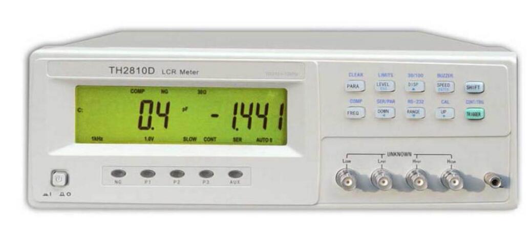
LCR digital bridge provides stable 6-bit test resolution, 10Hz-300kHz frequency range, 0.01V-2.0V programmable signal level, up to 30 times/second measurement speed, 9-level fine range, constant 30Ω or 100Ω source internal resistance and flexible human operation mode can meet the production line quality assurance, incoming inspection and laboratory.
LCR digital bridges can be used in the metrology and testing department for the verification and transmission of impedance gauges, as well as conventional measurements of impedance components in the general sector. Many digital bridges have a standard interface that automatically divides the component under test according to the accuracy of the measured value. It can also be directly connected to the automatic test system for automatic inspection of the product on the component production line to achieve the production process. QC. In the mid-1980s, there were dozens of digital bridges with a common error of less than 0.1%. Digital bridges are evolving toward greater accuracy, more functionality, speed, integration, and intelligence.
Passive components: Impedance parameter measurements for capacitors, inductors, cores, resistors, transformers, chip components, and network components.
Semiconductor components: Impedance parameter measurements of capacitors, inductors, magnetic cores, resistors, transformers, chip components, and network components.
Other components: impedance evaluation of printed circuit boards, relays, switches, cables, batteries, etc.
Dielectric materials: Loss angle evaluation of the dielectric constant of plastics, ceramics and other materials.
Magnetic Materials: Assessment of magnetic permeability and loss angle of ferrite, amorphous and other magnetic materials.
Semiconductor materials: dielectric constant, conductivity and CV characteristics of semiconductor materials.
Liquid crystal material: CV characteristics such as a dielectric constant and a spring constant of a liquid crystal cell.
The ultra-thin precision cutting of the Anti-Peep Screen Protector means that you can enjoy a perfect touch screen experience without allowing anything on the screen to be peeped. Whether you place your phone horizontally or vertically, Privacy Screen Protector can protect your personal Information and sensitive information are protected from harm by strangers. People around you cannot see the contents of your phone, so your details are safe.
The use of soft TPU material can really cover the entire screen.
With self-healing function, it can automatically repair bubbles and scratches within 24 hours.
The 0.14mm Ultra-Thin Protective Film can maintain the sensitivity of the touch screen to accurately respond to your touch.
The oleophobic and waterproof coating prevents fingerprints, oil stains and other substances from adhering to it and keeps the screen clean.
If you want to know more about Privacy Screen Protector products, please click Product Details to view the parameters, models, pictures, prices and other information about Privacy Screen Protector products.
Whether you are a group or an individual, we will try our best to provide you with accurate and comprehensive information about Privacy Screen Protector!
Anti-Spy Hydrogel Screen Protector, Privacy Protection Film, Protection Film, Privacy Film, Privacy Screen Protective Film, Soft Film
Shenzhen Jianjiantong Technology Co., Ltd. , https://www.tpuscreenprotector.com