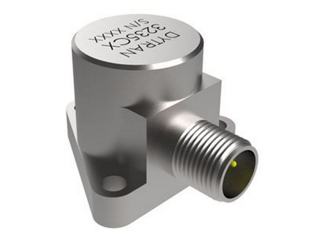
Sensor sensitivity, low frequency noise characteristics and dynamic response range
The physical parameters of the engineering vibration value are often expressed as displacement, velocity, and acceleration. Because the magnitude of the vibration displacement amplitude is small in the normal frequency range, and the displacement, velocity and acceleration can be mutually converted, the magnitude of vibration in actual use is generally measured by the value of acceleration. Commonly used units are: m/s2 (m/s2), or gravitational acceleration (g).
Another important parameter describing the vibration signal is the frequency of the signal. The vast majority of engineering vibration signals can be decomposed into a series of sinusoidal signals of a specific frequency and amplitude. Therefore, the measurement of a vibration signal is actually a measurement of the sinusoidal frequency component that makes up the vibration signal. The evaluation of the major performance indicators of the sensor is also based on the accuracy of the sensor in its specified frequency range.
Charge output accelerometers are not suitable for low frequency measurements
Because the low-frequency vibration acceleration signals are very small, and the high-impedance small charge signals are very susceptible to interference; when the measurement object's volume is larger, the lower its measurement frequency, the signal's SNR is more prominent. Therefore, in the current situation that the acceleration sensor with built-in circuit is becoming more and more common, a low-impedance voltage output piezoelectric acceleration sensor with low electric noise and excellent low frequency characteristics should be selected as far as possible.
Low-frequency cutoff frequency of the sensor
Similar to the high frequency cutoff frequency of the sensor, the low frequency cutoff frequency refers to the lowest frequency signal that the sensor can measure within the specified sensor frequency response amplitude error (±5%, ±10%, or ±3dB). The larger the error, the lower the low frequency cutoff frequency is. Therefore, the low-frequency cutoff frequency indicators of different sensors must be compared under the same error conditions.
The low-frequency characteristics of low-impedance voltage output sensors are determined by the integrated electrical parameters of the sensor's sensitive core and built-in circuitry. Its frequency response characteristics can be described by the first-order high-pass filter characteristics of the analog circuit, so the low frequency response and cutoff frequency of the sensor can be completely determined by the time constant of the first-order system. From a practical point of view, because the calibration of the sensor's VLF frequency response is difficult, the time constant of the sensor can be measured by the response of the sensor to the step signal in the time domain; therefore, the low frequency response of the sensor and the first-order high-pass filter are utilized. Features are almost identical, and the low-frequency response of the sensor and the corresponding low-frequency cut-off frequency can be easily obtained by calculation.
Sensor sensitivity, low frequency noise characteristics and dynamic response range
Sensors for low-frequency measurement generally require a relatively high sensitivity to meet the measurement of low-frequency small signals. However, the increase in sensitivity is often limited. Although the sensitivity of the acceleration sensor can reach 10V/g or more, the high sensitivity often brings other negative effects, such as the stability of the sensor, the ability of overload resistance, and the sensitivity to interference with the surrounding environment. Therefore, the pursuit of high sensitivity does not necessarily solve the measurement of small signals. On the contrary, high-resolution and low-noise sensors are often easier to solve practical problems in engineering applications. Therefore, the use of sensors with low electrical noise is particularly important in low frequency measurements.
In order to show that the sensor can measure the smallest signal, most commercially available accelerometers also provide resolution or electrical noise indicators. The broadband electric noise index of most sensors in China is generally marked as 20μV, and the broadband electric noise index of BW-sensor has been reduced to 10μV. However, for low-frequency small-signal measurements, providing only wide-band electrical noise does not fully reflect the sensor's resolution of the acceleration measurement in the low-frequency range; this is because the low-frequency noise caused by the built-in circuit is proportional to the inverse of the frequency, ie, The so-called 1/f noise, when the measurement frequency is very low, the electrical noise output of the sensor increases exponentially. Therefore, the value of the sensor's low-frequency electrical noise and the broadband electrical noise are completely different, and the lower the frequency, the more obvious this difference is. Therefore, the resolution of a sensor used for very low frequency measurement is often expressed as the power spectral density of the output electrical noise of the sensor. The practical significance of this indicator is the noise level of the sensor at a specific frequency. The unit is generally expressed in μV/√Hz or μg/√Hz. The typical power spectral density of the electrical noise in the built-in circuit of the BW-sensor is 3μV/√Hz@10Hz.

Transient Temperature Response of Sensors Affects Low Frequency Measurements
Because of the characteristics of piezoelectric ceramics, piezoelectric accelerometers produce varying degrees of charge output for sudden changes in temperature. The sensor's transient temperature response indicator measures the sensor's sensitivity to temperature changes. This is especially important for low frequency measurements. Because the low-frequency measurement signal is very small, and the sensor is likely to produce the same error as the low-frequency vibration signal due to the ambient temperature change; these two signals are difficult to distinguish in the very low frequency range, so how to reduce the influence of the ambient temperature changes on the sensor output It is very important in low frequency measurement. The unit of the transient temperature response of the sensor is g/oC, which represents the equivalent acceleration output for each degree of change in transient temperature. The value is obtained by converting the voltage (charge) output to the sensor sensitivity.
The transient temperature response of the sensor is directly caused by the piezoelectric material. Therefore, the size of the piezoceramic's charge output due to the temperature change determines the quality of this indicator. BW-sensor adopts the best piezoelectric ceramics with comprehensive performance indicators in foreign countries and combines with accelerometers made of memory metal for low-frequency measurement. It has been proved that sensors have excellent low-frequency output stability after many years of use in defense weapons, aerospace and large-scale structures. And anti-jamming performance. In the actual VLF measurement, in order to reduce the effect of the environmental temperature change on the output of the sensor's low-frequency signal, the outer casing of the sensor should be insulated as much as possible.
Sensor Mounting Base and Base Strain Affects Measurement
Because low-frequency measurement sensors do not have high requirements for high-frequency response, the sensors generally meet the requirements of any kind of installation. However, there are two issues to be aware of. One is that the sensor should consider the use of an insulating base as much as possible to avoid any influence of the noise caused by the ground loop on the measurement signal. The second is to consider the influence of the tested structure's strain on the sensor output at the sensor installation, ie the sensor's strain sensitivity. The piezoelectric acceleration sensor in the form of a shear structure has a good pedestal strain characteristic and can generally satisfy the usual low frequency structure test. If the strain of the structure is too large to affect the measurement signal of the sensor, the influence of the structural strain on the measurement of the sensor can be reduced by reducing the contact area between the sensor and the measured structure.
Corresponding to the sensor high-frequency index, the low-frequency measurement index of the sensor is usually determined by the low-frequency cut-off frequency, and a certain low-frequency cut-off frequency is also related to the corresponding amplitude error. Unlike high-frequency characteristics, the low-frequency characteristics of the sensor are independent of any mechanical parameters of the sensor, and only depend on the electrical characteristics of the sensor. Of course, the sensor as a part of the measurement system, the low-frequency characteristics of the measurement signal will also be constrained by the electrical parameters of the subsequent instrument used with the sensor. According to the different forms of output signals, the charge output and low-resistance voltage output acceleration sensors will be separately discussed below.
Although the charge-type output acceleration sensor lists the low-frequency cut-off frequency, it generally gives low-frequency characteristics indicating the measured signal to be determined by the subsequent charge amplifier. In practical applications, when the insulation resistance of the core of the charge-type sensor is much larger than the input impedance of the input of the charge amplifier, the low-frequency cut-off frequency of the measurement system composed of the sensor and the charge amplifier should be determined by the low-frequency characteristics of the charge amplifier. However, if the core insulation resistance of the sensor decreases, the sensor may affect the low frequency characteristics of the entire measurement system. Therefore, it is very important to ensure that the insulation resistance of the core is low-frequency measurement of the charge output type acceleration sensor.
For IEPE sensors with a constant current voltage source, the usual low frequency cut-off frequency is 0.1 Hz (-5%). Therefore, the low frequency characteristic of the measurement system is generally determined by the low frequency end frequency of the sensor. The low-frequency cut-off frequency of general-purpose sensors is mostly 0.5Hz~1Hz, and the low-frequency cut-off frequency of sensors specially designed for low-frequency measurement can be extended to 0.1Hz. Because of the difficulty of low-frequency calibration of sensors, manufacturers generally only provide test data above 10Hz. However, the low-frequency characteristics of the sensor are very consistent with the first-order high-pass filter, so users can check the actual low frequency response of the sensor by measuring the time constant.
With IEPE piezoelectric acceleration sensor to measure very low frequency acceleration signals also need to pay attention to the problem are:
When the AC and low frequency cut-off frequencies of the AC-coupled sensor and the constant current voltage source are equivalent, the low-frequency characteristic of the measurement system is formed by the respective low-frequency response of the sensor and the constant current voltage source. At this time, the low frequency cut-off frequency of the measurement system is higher than that of the sensor or The respective low frequency cutoff frequency of the constant current voltage source. The ideal measurement system sensor should be equipped with a constant current voltage source with DC balance so that the low frequency response of the system will depend entirely on the low frequency cut-off frequency of the sensor.
When the sensor is used for very low frequency measurement, whether the low frequency signal can be accurately measured does not completely determine the low frequency response characteristics of the system, and the low frequency electrical noise of the system will also directly affect the measurement of the low frequency signal. In addition, the transient temperature response of the sensor will also directly affect the low frequency measurement of the sensor.

15v wall charger,15 Watt Power Supply,15v ac dc adapter,AC Wall Charger Power Adapter,AC/DC Charger Power Supply Switching Adapter,DC 15V Global AC / DC Adapter,15VDC Power Supply Cord Cable Wall Charger,15VDC800 Charger PSU
Shenzhen Waweis Technology Co., Ltd. , https://www.waweis.com