Tianfan CAN bus faults
Tianzhu is a flagship mid- to high-end luxury sedan under the NISSAN umbrella. With a brand new technology, Scorpio made a perfect match between Driving Technology and Comfort Technology to bring the design concept of midsize cars to a new level. This article first introduced the Tianzhu CAN bus fault (IPDM fault), followed by a description of the Nissan Teana 2.3 car unable to start the troubleshooting solution, and finally elaborated the Dongfeng Nissan Scorpio accelerated failure phenomenon and what is the reason, the specific follow Xiaobian together Learn about.
One, IPDM failureFault phenomenon
A Dongfeng Nissan Scorpio 2.3L sedan, the user reported that the car was shut down normally, the following failure occurred on the second day after starting again: Turn on the ignition switch or the fan is always turning after the car; without turning on the light switch, the headlight is near. The light is always on and the dimming switch is switched on. The light cannot be changed. After starting the air conditioner, the air outlet of the air conditioner emits hot air.
Failure analysis
The maintenance personnel first connected the fault diagnostic machine to scan the entire vehicle. The fault code meaning “CAN communication circuit fault†was stored in both the engine control unit ECM and the body control unit BCM, and was not cleared. Except for the fault codes in the above two control units, the other systems have no fault. According to this analysis, the fault of the vehicle should be the data transmission error between the control units caused by the failure of the CAN communication network and the activation of the protection mode of the vehicle.
The maintenance personnel consulted the network topology (Figure 2) to understand the communication connection mode of the car control unit, and through the information that the car's terminal resistance in the ECM and IPDM (Intelligent Power Distribution Module). Under normal conditions, these two termination resistors are in parallel. The fault of this car belongs to the network communication failure, and should pay attention to the following two aspects: The power supply of the control unit and the communication line of the control unit.
According to the "CAN circuit failure" fault code, the maintenance personnel decided to check the terminating resistance of the vehicle network first. After removing the battery cable, measure the resistance between CAN-H and CAN-L from the diagnostic seat. The result is 142 Q. The normal value should be 60~70 Q. The CAN network terminating resistor is composed of two parallel 120Ω resistors. Therefore, based on the measurement result, it is inferred that there is a possibility that the network communication circuit is disconnected or the terminating resistor in a control unit is disconnected.
As mentioned earlier, the two terminating resistors are in the ECM and the IPDM, so the maintenance personnel remove the IPDM (located in the right front of the engine room and behind the right headlight). The internal terminating resistance of the IPDM is normal, which is 140 Q. Continue to measure the terminating resistance of the CAN connector in the harness connector. The result is 142 Q, indicating that the harness is normal. From this reasoning, the IPDM's CAN line connector should be in poor contact or open circuit. After careful observation, it was found that the terminal of the IPDM connector harness side socket was deformed and loosened.
Troubleshooting
After handling the connector, the resistance between CAN-H and CAN-L is again measured from the diagnostic socket and the resistance is 70 Q. Install the battery cable to turn on the ignition switch. The above-mentioned fault phenomenon disappears. At this time, the fault diagnosis code is used to clear the fault code. The above troubleshooting of CAN communication can be cleared. After the trial run, everything was normal and the car was troubleshooting.
Review and summary
This vehicle fault is caused by a poor contact between the jack terminal corresponding to the resistance of the CAN terminal and the IPDM in the IPDM harness side connector.
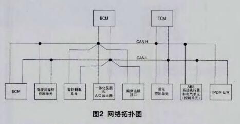
For the CAN data bus problem, we should first understand the structure and composition of the vehicle's CAN network. The CAN terminal resistance of the vehicle is in the IPDM and ECU respectively. Detecting the terminating resistor is one of the effective methods to eliminate network faults.
When the car's network communication fails, the way to enter the emergency state is as follows: After turning on the key or the car, the fan rotates normally; The headlights can be turned on and the light can not be changed; The air conditioner is not cooled.
Second, the Nissan Teana sedan 2.3 does not startA Nissan Teana 2.3 car with a mileage of approximately 77,000 kilometers. User feedback: The car could not start.
Troubleshooting:
1) The battery and starter motor are in good condition. It is not possible to start up. Initial inspections revealed that there was a problem with the anti-theft system and they were dragged back to my shop.
2) Connect the diagnostic computer and read the fault code: P1610, P1614 two fault codes.
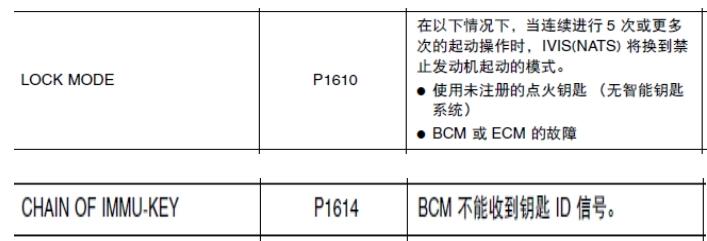
3) To eliminate the code, the fault code P1614 is gone, leaving only P1610 and it cannot be eliminated. The failure code list on the previous page indicates that the failure may be a non-matching key, BCM, ECM, etc.
4) Then we first tried to match the key, but the NATS system could not be initialized. The suspicion is not that the key chip is damaged, so the key is changed and still cannot be initialized.
5) Then consider the common BCM of the 2 fault codes on the previous page, find the BCM of the 2004 Tianchan of the accident workshop and change it, and then carry out key matching. If the initialization is successful, it means that there is a problem with the BCM, and then it is equipped with a mechanical key.
6) Insert the mechanical key, turn on the ignition switch, the security light does not flash 5 times, but it can start. Then start with the smart key, the vehicle can not start, still put the mechanical key into the lock cylinder, can not start, while seeing the red light of the KEY on the left of the instrument flashes, indicating that the key match did not succeed.
7) At this time maintenance is in trouble. Think BCM can be initialized, the general direction is right, there may be small details did not take into account, so carefully look at the circuit diagram and found that BCM pins 04 and 06 have a difference, 04 NATS amplifier corresponding to BCM is Numbers 23 and 25, while 06 NATS amplifiers for BCMs are numbers 21 and 25 (attached figure).
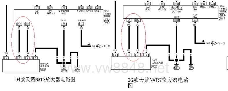
8) After discovering this small difference, the BCM for 2006 will be matched with the mechanical key again, and the anti-theft light will flash 5 times. The match is successful. The vehicle can be started several times and troubleshooting can be started.
Maintenance summary:
1. When diagnosing the vehicle at the time, taking into account that the two vehicles did not change much, and the NATS system was the same, it was always referring to the circuit diagram of the 04 section, which made maintenance difficult.
2, is also due to the same reason, the swap BCM is also 04, so artificially set the fault.
3. In the course of future maintenance, reference should be made to the data for the corresponding year. Subjects should not be subjective to look at the data before or after the change. The replacement parts should also be the same. In order to avoid causing mistakes in maintenance.
Three, Dongfeng Nissan Teana Accelerates PowerlessnessFault phenomenon:
A Scorpio 2.3L sedan is equipped with a RE4F04B 4-speed electronically controlled automatic transmission with a total length of 86,000 km. The user reported that the car was poorly accelerated and the vehicle had a feeling of shock.
Check analysis:
The maintenance personnel first performed a test run. After the car started, when the engine was accelerated to 30 kmh, the engine speed could be normally increased, but the vehicle speed was slow; the acceleration was continued to 40 to 50 kmh. At this time, the transmission had a large impact. After the impact, the vehicle became It is stable, and the speed of the vehicle is increased quickly; when the vehicle speed drops to 20kmh again, the above-mentioned acceleration phenomenon will occur again. Based on this, maintenance personnel should analyze the fault and should belong to the category of automatic transmissions.
Maintenance personnel began the routine inspection of the automatic transmission: first check the oil quality of the ATF and found that the color of the ATF was black. After the stall test, the stall speed of the engine was 2400 rmin, and the normal stall speed was around 2100 rmin, indicating that there was a slight slip. The detector was used for detection. No fault code was stored. The AT data stream was observed and the shift was normal. However, the gear ratio at the 2nd gear was abnormal.
The maintenance personnel used the lift to lift the vehicle up to a certain height. The speed of the vehicle was raised quickly and the impact was noticeably reduced. However, the ATF oil pressure was constant during the operation of the gears and they were all around 600kPa (normal condition, oil pressure). Should vary with throttle opening and vehicle load between 500 and 1200 kPa). Based on the above inspection results, maintenance personnel analyzed the cause of the transmission failure because the main oil pressure was insufficient to cause partial elements to slip at the time of acceleration, and the friction parts inside the transmission were damaged due to accumulated over time. The maintenance personnel disassembled the transmission and found that the brake band, high-speed clutch plate, reverse clutch drum, and 2-speed brake drum were all damaged.
The primary task now is to find the cause of low oil pressure, otherwise the fault cannot be completely eliminated. According to the previous inspection results, the maintenance personnel analyzed the direct cause of the failure that the main hydraulic pressure could not increase with the increase of the vehicle load, resulting in abnormal wear of parts of the friction parts when the vehicle was climbing or rapidly accelerating. It was not easy to find in the early stage and the wear and tear became worse over time. Until damage.
Components related to the main hydraulic pressure include hydraulic solenoid valves, oil pumps, and main hydraulic pressure related components in the valve body. After inspection of the oil pump, the maintenance personnel replaced the valve body assembly (including the oil pressure regulating valve, etc.), the line pressure solenoid valve and the shift solenoid valve, and replaced the worn brake band, high-speed clutch plate, and reverse clutch drum. And 2 speed brake drum.
After the transmission was refitted and tested, the vehicle failed to upshift, and the transmission only operated in the first gear. When the large throttle accelerated the vehicle to 50kmh, it was only occasionally upshifted. This situation is usually caused by no vehicle speed signal or out of control of the control unit. After careful inspection, the maintenance personnel found that the speed sensor and the input speed sensor plug were incorrectly inserted. The two sensor plugs were the same and were in close proximity. The maintenance personnel neglected to insert the plug for the moment, resulting in a signal error and unable to perform the shifting work. After the maintenance personnel exchanged the plugs and tested, they found that there was still a slip phenomenon when the second gear was applied. When the inspection found that the oil pressure was insufficient in the second gear, the oil pressure in other gears was normal.
The maintenance personnel analyzed the transmission path of the second gear. The transmission was a four-speed Simpson type planetary gear structure. The forward gear clutch engaged at the second gear, the forward gear one-way clutch, the brake belt working, and the input shaft connected to the rear sun gear. The power is transmitted through the pinion (planetary gear) to the rear internal gear (inner ring gear), and then is connected with the front planetary gear carrier via the forward gear one-way clutch and the forward gear clutch. At this time, the front sun gear is locked by the brake band. The internal gear and the rear carrier are connected to the output shaft to output power.
According to the above 2 block transmission route, the maintenance personnel should analyze that the brake band is not working properly, resulting in slippage in the 2nd gear. Then the maintenance personnel removed the transmission and inspected the relevant parts of the brake belt. When the compressed air was used to pressurize the hydraulic chamber of the servo cylinder to block the oil pressure chamber, there was no apparent working sign of the servo, indicating pressure relief. After careful investigation, the server was found. Damage to the 2nd stop seal apron may be caused by accidental damage when replacing parts in the automatic transmission overhaul kit (including various sealants and gaskets).

Accessories For Power Line Stringing
Accessories For Power Line Stringing Series of various types including Continuous Duct Rods,Fiberglass Duct Rods,Earth Drill,Earth Anchor,Pulling Socks,Joint Protector,Pole Climber,Wrenches,Conductor Spacer,Spacer Bike,Aluminum Ladder,etc,which is widely used in power line project.All of them are made of high quality materials with reasonable volume,light weight,easy to operate.By high quality material and good design,these kind of tools can be durable and long service life.we are a professional Chinese exporter of Electric Power Line Stringing Tools,and we are looking forward to your cooperation.
Yangzhou Qianyuan Electric Equipment Manufacturing & Trade Co. Ltd is specialized in manufacturing and trade of electric power line transmission tools. Our main products are Anti-twisting Steel Wire Rope,Stringing Pulley,Hydraulic Crimping Compressors,Engine Powered Winch,Motorised Winch,Wire Grip,Gin Pole,Cable Stand,Mesh Sock Grips,Cable Conveyor,Lever Chain Hoists and so on,which are mainly supplied to power companies,railroad companies and other industry fields.
All our products are certified by China National Institute.To assure the quality, we will do 100% inspection for raw material, production procedure, packing before shipment,
so we do have the confidence to supply customers with high-quality and high-efficiency products.
"Customer satisfaction" is our marketing purposes,so we have extensive experience in professional sales force,and strongly good pre-sale, after-sale service to clients. We can completely meet with customers' requirements and cooperate with each other perfectly to win the market.Sincerely welcome customers and friends throughout the world to our company,We strive hard to provide customer with high quality products and best service.
Accessories For Power Line Stringing,fiberglass duct rodder,safety helmet,Joint Protector,pole climbers
Yangzhou Qianyuan Electric Equipment Manufacturing & Trade Co.Ltd , https://www.qypowerline.com