What if there is no Pmod driver directly available? Teach you a trick
Previously we mentioned the "Pmod Sensing Module", a tool for rapid prototyping system development with an FPGA development board. In fact, in addition to the nearly 100 kinds of feature-rich original Pmod sensor modules provided by Digilent, the patented interface of the Pmod standard definition interface (generally equipped with a free ip driver for developers to call directly), on the market There are many Pmod modules available from different vendors.
Many Pmods from unknown small factories (mostly in Taiwan and Shenzhen) often do not provide module drivers, and users need to write drivers to fill the pits. If you are unfortunate enough to take the opportunity to talk about comfort, today I will teach you a trick to fill the pit and teach you how to deal with it without a driver available.
Let me focus first: If there is no driver available, you can use the Zynq SoC PL (programmable logic) Pmod bridge module, which allows us to establish the correct mapping between the selected development board and the Pmod port, and then develop our own Zynq PS (Processing System) driver. If you look closely at the Pmod drivers provided by regular vendors, you will find that these drivers are actually implemented using the Pmod bridge plus an AXI I2C or SPI component.
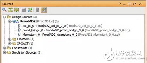
Figure: Digilent PmodAD2: Driver component for a 12-bit four-channel analog-to-digital converter
In this article, we will take the Digilent PmodDA4: 8-channel DAC module and the PmodAD2: 4-channel ADC module as an example. We will integrate these two modules and develop the driver ourselves with the Pmod bridge module, using PmodDA4. Generate an analog signal and use PmodAD2 to receive the signal.
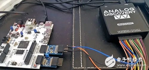
Figure: Testing the PmodDA4 with the Digilent Analog Discovery pocket instrument
The Pmod Bridge module allows us to define the input type of the upper and lower rows of the Pmod interface on the development board. It can be selected as GPIO, UART, I2C or SPI protocol interface. We select and configure the upper and lower layers of the onboard Pmod interface for the required driver, so that the pinout of the Pmod sensor is consistent with the corresponding onboard interface standard. Interested friends, click "Read the original" to download the interface standard documentation for the Digilent Pmod sensor.
For PmodDA4, we only need to use the SPI protocol on top of the onboard Pmod interface. With this choice, we need to provide the actual SPI communication channel. Since we are using the Zynq SoC development board (Digilent Arty Z7), we have two options here. The first method is to establish a connection with the Pmod bridge module using the AXI SPI IP module on the PL side. The second method (which we will use here) is to use EMIO to establish a connection between the Zynq PS SPI and the Pmod bridge. This approach will allow us to establish a direct connection between the PS SPI port and the Pmod bridge module input pins.
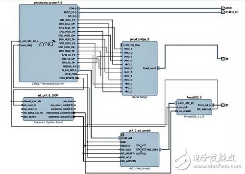
To do this we need to read the official Pmod interface standard documentation to ensure proper mapping between the SPI pins and the Pmod bridge input pins (eg which PS SPI signal is connected to IN_0). The pins of the Pmod bridge module represent different interface types, and their naming is also common. The block diagram below shows how we can implement the PmodDA4 pin mapping here. In this example, we can build the project after completing the pin mapping, export to the SDK, and write the software program to drive DA4.
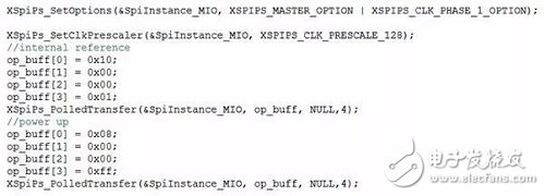
We can use the SPI driver created by the BSP in the SDK to drive the PmodDA4. In order to interact with PmodDA4, the first thing we have to do is initialize the SPI controller. Once we have set the SPI clock phase and main operating options, we can define the buffer and use the polling transfer mode to pass the required information to PmodDA4. More complex drivers will use interrupt-driven rather than polling.
Below, we tested the created PmodDA4 driver file. We drive a simple harmonic output and use the oscilloscope function of the Digilent Analog Discovery pocket instrument to monitor the DAC output. The received signals are as follows:
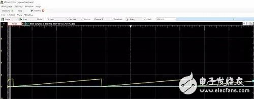
After completing all the settings PmodDA4 works as expected, then we connect PmodDA4 with PmodAD2 so that the Zynq SoC can receive the signal:
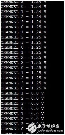
We have to be very careful during the test to ensure that the PmodDA4 output signal is within the working range of PmodAD2. When completed, PmodDA4 will work properly on the hardware.
At this point, I believe you have already learned how to create a Pmod driver yourself without an available driver. Of course, filling the pit is often a last resort, life is too short, Fanghua is limited, as far as possible to touch the small cottage Pmod is the king.
Iphone Screen Protector,Tempered Glass,Privacy Tempered Glass,Hydrogel Screen
Shenzhen TUOLI Electronic Technology Co., Ltd. , https://www.szhydrogelprotector.com