Overall analysis and specific interpretation method of PLC ladder diagram
1, system analysis
According to the control tasks required by the control system, the process, working characteristics of the controlled object, and the control process, control rules, functions and features of the control system are analyzed in detail to determine whether the input and output physical quantities are switching or analog. Divide the various stages of control and its characteristics, the transition conditions between the stages, draw a complete work flow chart and the action beat table of each actuator.
2, look at the main circuit
Learn more about the process flow and its corresponding actuators.
3. Look at the I/O configuration of the control system and the I/O wiring of the PLC.
Understand the configuration of the input signal and corresponding input, the configuration of the output relay, and the corresponding load to which it is connected. In the case where the input/output device definition and the PLC's I/O configuration are not given, the input/output device definition and PLC I/O should be made according to the PLC's I/O wiring diagram or ladder diagram and instruction statement table. Configuration.
4, through the PLC I / O wiring diagram to understand the ladder diagram
The I/O wiring of the PLC is the link between the main circuit and the PLC ladder diagram.
(1) According to the main symbol of the main circuit of the appliance (such as solenoid valve, electric heater, etc.) to control the main contact of the appliance (, relay), find the coil of the corresponding programming component in the I/O wiring diagram of the PLC. It can be known to control the output relay of the control appliance, and then find the block of the output relay in the ladder diagram or statement list, and mark and explain.
(2) According to the input device of the I/O wiring diagram of the PLC and its corresponding input relay, find the moving contact and the breaking contact of the input relay in the ladder diagram (or statement list) and mark accordingly. And instructions.
Second, the structural analysis of the ladder diagram1. Characteristics of ladder diagram of PLC control system
(1) Input signal and output load of PLC control system
The actuators in the relay and solenoid valves are controlled by the output relays of the PLC, and their coils are connected to the output of the PLC. Buttons, control switches, limit switches, proximity switches, etc. are used to provide control commands and feedback signals to the PLC, and their contacts are connected to the input of the PLC.
(2) Processing of the sum in the relay circuit diagram
The functions of the intermediate relay and time relay in the relay circuit diagram are completed by the auxiliary relays and timers inside the PLC, which are independent of the input and output relays of the PLC.
(3) Set the intermediate unit
In the ladder diagram, if multiple coils are controlled by a contact series/parallel circuit, in order to simplify the circuit, an auxiliary relay controlled by the circuit can be set in the ladder diagram, and the auxiliary relay is similar to the intermediate relay in the relay circuit. .
(4) Processing of time relay momentary contacts
In addition to the time-delayed contacts, the time relay also has a momentary contact that acts immediately when the coil is energized or de-energized. For time relays with momentary contacts, an auxiliary relay can be connected in parallel across the coil of the corresponding timer in the ladder diagram, the contact of which is equivalent to the momentary contact of the time relay.
(5) Establishment of external interlock circuit
In order to prevent the two contactors that control the forward/reverse operation from acting at the same time, causing a three-phase short circuit, in addition to the soft interlock circuit composed of the dynamic breaking contacts of the series of output relays corresponding to their corresponding output relays in the ladder diagram, Set a hard interlock circuit outside the PLC.
2. Structure analysis of ladder diagram
Use general programming method or sequential function chart programming method; use single-sequence structure of sequential function diagram or select sequence structure, parallel sequence structure, use start/stop/stop circuit, step sequence instruction for programming or set/reset The instructions are programmed. See Chapters 4 and 5 for this part.
The decomposition of the ladder diagram is started by the operation master circuit (such as a button), and the line is traced to the main circuit control device (such as the contactor). The middle of the circuit has to go through many programming components and circuits, which is difficult to find.
No matter how complicated the ladder diagram is, it is composed of some basic units. According to the composition of the main circuit, using the reverse reading source method, the ladder diagram and the instruction statement table are decomposed into several basic units corresponding to the main electrical equipment (such as the motor), and then analyzed in one link and one step. Then use the tracking method to string together the links.
(1) Configuration and function of buttons, stroke switches and transfer switches
There are many stroke switches and transfer switches in the I/O wiring diagram of the PLC, as well as pressure relays, temperature relays, etc. These electrical components do not attract coils, and the action of their contacts is realized by external force or other factors, so it must first Find the external force or factor that causes these contacts to act. The travel switch is touched or released by the mechanical linkage mechanism, and the changeover switch is generally operated manually, so that the contacts of the travel switch and the changeover switch are in different working states during the operation of the device, that is, the closing of the contact. The disconnection is different to meet different control requirements, which is a key in the process of viewing the picture.
The different working states of the contacts of these travel switches and transfer switches are difficult to understand by looking at the circuit diagram. It is necessary to combine the equipment manual and the electrical component list to clarify the purpose of the travel switch and the changeover switch, and to operate the mechanical linkage mechanism of the travel switch. Point the operating state of the circuit in different closed or open states.
(2) Decomposition of multiple loads (such as multi-motor circuits) into single-load (such as single-motor) circuits using reverse-reading traceability
According to the main contact word symbol of the control appliance that controls the load in the main circuit, find the output relay of the contactor coil that controls the load in the I/O wiring diagram of the PLC, and then find the control in the ladder diagram and the instruction statement table. The coil of the output relay and its associated circuitry, which is the partial circuit that controls the load.
In the ladder diagram and the instruction statement table, it is easy to find the coil circuit of the output relay and its power-off and power-off conditions, but the power generation and power loss of the coil and related circuits are not easy to find, and the reverse reading can be adopted. Traceability method to find:
1 In the output relay coil circuit, the closing and opening of the other programming component contacts in series or parallel is the condition that the output relay is powered and de-energized.
2 These contacts are used to find their coil circuits and their associated circuits. There are also contacts for other contactors and relays in these coil circuits.
3 Look for it until you find the input relay (main power).
It is worth noting that when a programming component is electrically disconnected or de-energized, the working states of the front and rear programming components driven by all the contacts of the programming component should be found out and must not be missed.
Find the moving contact and breaking contact of a programming component in other circuits. These contacts provide conditions for powering and de-energizing other programming components or provide conditions for interlocking and interlocking, causing other electrical components to operate. Drive the appliance.
(3) Further decompose the single load circuit
The local circuitry that controls a single load can still be complex and requires further decomposition until it is broken down into basic unit circuits.
(4) Considerations for the decomposition circuit
1 If the motor shaft is connected with a speed relay, the motor constitutes a parking brake circuit according to the speed control principle.
2 If a rectifier is connected to the main circuit of the motor, it indicates that the motor uses a dynamic braking circuit.
(5) Set zero as a whole, comprehensive analysis
The basic unit circuits are stringed together, and the entire circuit is analyzed by the read-and-follow tracking method.
Third, the specific method of reading the ladder diagramThe process of reading the PLC ladder diagram and the statement list is the same as that of the PLC scanning user process. From left to right, top to bottom, the diagram is read piece by piece in the order of the block.
It is worth pointing out that during the execution of the program, in the same cycle, the previous logical operation results affect the subsequent contacts, that is, the executed program uses the latest intermediate operation result. But within the same week, the results of the subsequent logical operations do not affect the previous logical relationship. The final state of all internal relays except the input relay during the scan cycle (the coil is turned on or off, the contact is turned on or off) will affect the on and off of each contact in the next scan cycle.
Since many readers are familiar with the relay contactor control circuit, it is recommended to follow the readout relay contactor control circuit to check the line reading method, and follow the steps below to see the ladder diagram:
1. According to the I/O allocation table and ladder diagram of I/O equipment and PLC, find the input and output relays, and give the text code corresponding to the relay contactor control circuit.
2. Mark the text code of the corresponding input device and output device next to the ladder programming component coil and its contacts.
3. Decompose the ladder diagram into several basic units, each of which can be a block of ladder diagram (including one output component) or several blocks (including several output components), and each basic unit is equivalent to a relay A branch circuit of the contactor control circuit.
4. The corresponding relay contactor control circuit can be drawn for each step.
5. A programming component is energized, all of its moving contacts are closed, and the breaking contacts are all disconnected. When a programming component loses power, all its closed moving contacts are open (reset) and all disconnected dynamic contacts are closed (reset). Therefore, after the programming component is powered or de-energized, all its moving and closing contacts and the breaking contacts are found out, and the influence on the corresponding programming components is analyzed.
6. In general, the ladder diagram can be read from the first natural line of the first block. The first natural behavior program starts the line. Press the start button to turn on an input relay, all the moving contacts of the input relay are closed, and the break contacts are open.
Then find the programming components affected by the input relay closing contact and the breaking contact opening, and analyze what actions these programming components produce to determine the function of these programming components. It is worth noting that some of these programming components may be powered immediately, and some do not act immediately but are prepared for their energization.
It can be known from the working principle of the PLC that when the input terminal is connected to the contact, when the PLC is working, if the moving contact of the input end is closed, the input relay coil corresponding to the input terminal is energized, and its moving contact is closed. The breaking contact is disconnected; when the input terminal is connected to the breaking contact and is working in the PLC, if the breaking contact of the input end does not operate, the input relay coil corresponding to the input terminal is energized, and its moving contact The closed, break contact is open.
If the break contact is in series with the output relay coil, the output relay coil cannot be energized. Therefore, the PLC is used to control the start and stop of the motor. If the stop button is used for the break contact, the PLC output relay coil connected to the contactor of the control motor should be connected in series with the active contact corresponding to the input terminal connected to the stop button. .
In the relay contact control, the stop button and the break contact are both used. In order to be consistent with the control circuit of the relay contact control, in the PLC ladder diagram, the break contact is also used, so that the input terminal The stop button and the thermal relay contact must be used with the moving contact. You must pay attention to this when you read the program.
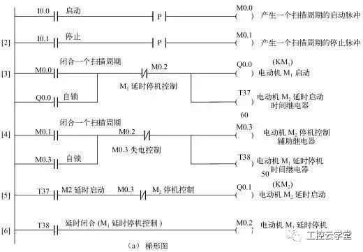
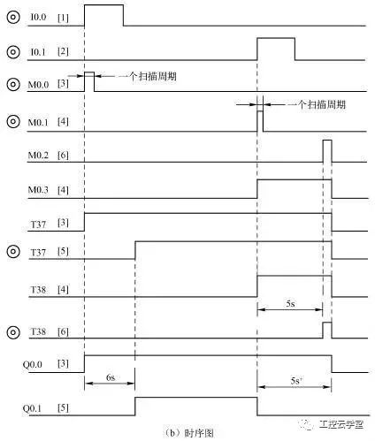
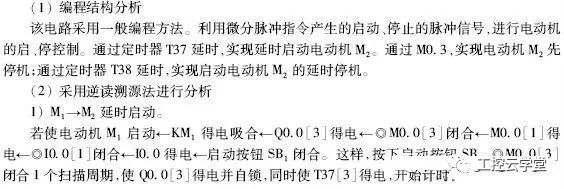
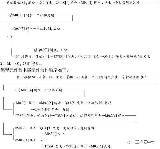
Fourth, read the example of PLC ladder diagramWhen analyzing the function of the PLC control system, it can be imagined as a control box in the relay control system. The external wiring diagram describes the external wiring of the control box. The ladder diagram or statement list is the internal "circuit diagram of this control box." "The input relay and output relay in the ladder diagram are the "interface relays" that this control box contacts the outside world, so that the PLC control system can be analyzed by analyzing the relay circuit diagram. In the analysis, the contact of the input relay in the ladder diagram can be imagined as the contact or circuit of the corresponding external input device, and the coil of the output relay is imagined as the coil of the corresponding external load. The coil of the external load may be controlled by the external contacts in addition to the control of the ladder diagram.


Transparent Led Film Screen P8
We are an enterprise with the whole industry chain of LED film screen display platform, which realizes the research and development of transparent film materials, independent patch production, assembly, sales and service. Products are mainly used in large glass curtain walls, city buildings, large shopping malls, glass guardrails, glass windows, shops along the street, automobile 4S stores, jewelry brand stores, brand clothing chain stores, unmanned supermarkets, indoor hanging and other fields.
Transparent Led Film Screen P8,Small Transparent Led Screen,Transparent Led Film,Transparent Led Wall
Guangdong Rayee Optoelectronic Technology Co.,Ltd. , https://www.rayeeled.com